What is 4-quadrant operation?
The 4 quadrants of an electric drive
The operation of an electric drive can be divided into four quadrants, defined by the combination of speed n and torque M:
Quadrant 1:
If speed is positive (n > 0) and torque is positive (M > 0), the drive is motoring in forward (clockwise) rotation.
Quadrant 2:
If speed is positive (n > 0) and torque is negative (M < 0), the drive is generating and braking while moving forward.
Quadrant 3:
If speed is negative (n < 0) and torque is negative (M < 0), the drive is motoring in reverse (counterclockwise) rotation.
Quadrant 4:
If speed is negative (n < 0) and torque is positive (M > 0), the drive is generating and braking while moving in reverse.
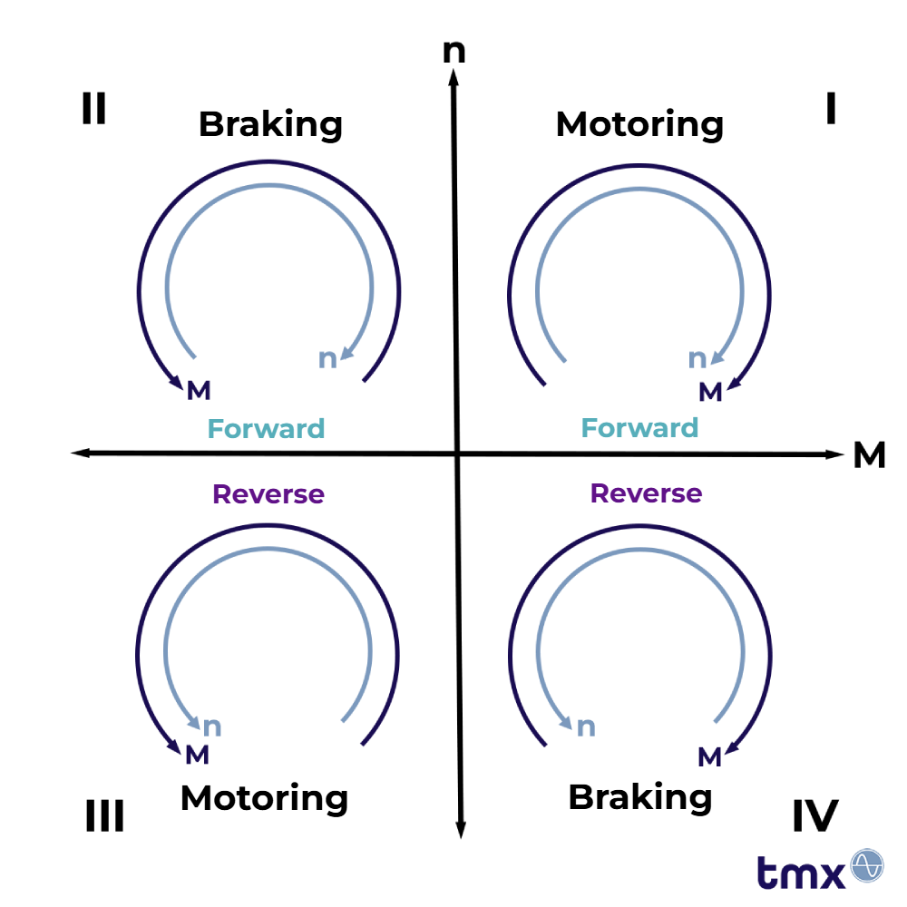
A drive and braking system that can operate in all four quadrants is called a 4-quadrant drive (4Q operation). In gearbox test stands and test stands for traction motors, we use this capability to run fully realistic load profiles, for example on our TMX truck and car transmission test stands, where the drive and load machines can swap roles dynamically. This lets you reproduce acceleration phases as well as coasting and regeneration without gaps.
Why does it matter?
- Realism: The gearbox experiences exactly the same load changes as on the road or in the drivetrain of a wind turbine.
- Efficiency: Regenerating quadrants feed energy back into the DC link or the public grid. This eliminates the need for braking resistors, heat sinks, water brakes, and similar equipment.
- Data quality: Fast switching between motoring and regeneration reveals backlash, bearing clearance, and resonances on the test stand.
How do we implement it?
Two motors are connected to the input and output shafts of the gearbox via couplings. Their two variable frequency drives share a common DC link. Surplus energy from the load machine is used to accelerate the drive machine. As a result, only the power losses need to be fed into the system from outside.
Several model-based controllers take inertia and gear mesh stiffness into account so that no torque peak occurs even when passing through gear backlash. In several loops, the model-based control first regulates the motor currents. Superimposed torque and speed controllers then vary the roles of drive and load machine dynamically during the test. Energy can flow in every direction: 4Q operation.
Result
With 4Q operation, we can reproduce highly dynamic drive cycles, stop-and-go city traffic, or downhill coasting with a tailwind in the lab so precisely that the measurement data can go straight into simulation and validation.
Curious?
Contact us. We'll gladly show you live how your individual load profile comes to life on a 4-quadrant test stand.
YOUR NEXT STEP
Get in touch
We look forward to learning about your test and measurement tasks and developing solutions together that take your projects to the next level.