We design the shaft train for the device under test, from the fast-spinning car drive motor to the ship propulsion motor.
Overview
What a traction motor test stand does
A traction motor has to withstand full load, heat and constant load changes for years. Whether it can is proven on the test stand.
We build these test stands: for drive motors in passenger cars and commercial vehicles and for traction motors in rail vehicles, construction machinery, agricultural machinery and ships. On a traction motor test stand the motor runs on a machine bed under real load. A load machine brakes or drives it while torque, speed, electrical power and temperatures are recorded. Characteristic curves, efficiency, thermal behavior and service life show what the motor can do before it is installed.
Large drives are our subject because they bring together everything that makes test stand engineering demanding:
High speeds, high torques
Power up to the megawatt range
Regeneration and back-to-back operation keep grid connection and energy costs in check.
Climate chambers with high heat input
Under load the motor gives off a lot of heat. Conditioned air and media conditioning keep test conditions stable.
Endurance runs over days
The software runs load profiles automatically and protects DUT and system through limit values.
We select load machine, inverter, measurement technology and climate equipment independently of any vendor, based on your test task.
Applications
What test stands for traction motors are used for
Traction motors get more compact and more powerful with every generation. Higher power density means higher speeds, more heat in less space and less margin in insulation and bearings. Whether a motor holds its data over its planned service life only shows under load. On the test stand that operation can be reproduced deliberately and repeatably.
Typical questions for the test stand:
- Does the motor reach the characteristic curve and efficiency from its design?
- How does it behave in heat, cold and rapid temperature changes?
- At which load, and after how long, does it overheat?
- Does it withstand the load spectrum over its service life?
- Does it work correctly with inverter and control?
Traction motor test stands are operated by vehicle and motor manufacturers, their suppliers, engineering service providers and research institutes, plus maintenance organizations: in rail maintenance, overhauled drive units are checked on the test stand before reinstallation.
Industries
Traction motor test stands in automotive, rail, construction machinery and shipping
Test stand technology for large electric motors is very similar across industries. Machine bed, shaft train, load machine, inverter, measurement technology and automation follow the same principles. The differences lie in power, speed and torque and in each industry's test regulations.
| Industry | Typical devices under test | What shapes the test stand |
|---|---|---|
| Automotive and commercial vehicles | Drive motors, e-axles, motor with inverter | High speeds, battery simulation, environmental simulation with temperature cycling, test programs to company standards |
| Rail | Traction motors, drive units of motor, gearbox and shaft | High torques, testing after overhaul; for inverter-fed traction motors, DIN EN 60349-2 as the reference |
| Construction and agricultural machinery | Drive and work drives | High torques |
| Shipping | Propulsion motors for hybrid and fully electric vessels | Power up to the megawatt range, several voltage levels (e.g. 400, 525 and 690 V), back-to-back operation |
Test procedures
Typical tests for traction motors
The tests a test stand has to perform determine its design. The following procedures are common for traction motors. Sequence and limit values come from the applicable standard, company standard or customer specification.
Characterization and development
- Characteristic curves and efficiency map
- Torque, power and efficiency over the full speed and torque range, motoring and generating. The basis for design and data sheet.
- Back-EMF (source voltage)
- The DUT is disconnected from the inverter and driven by the load machine. The induced voltage is measured at the open terminals at various speeds.
- Short-circuit test
- The DUT terminals are short-circuited and the load machine drives it to various speeds. The short-circuit currents are measured. Because torque can rise sharply, the load machine has to be rated for it.
- Thermal limits and derating
- At which load, and after how long, does the motor reach its temperature limits? Many drives then reduce power to protect themselves from overheating. This is called derating. The test stand shows when it starts and how strong it is.
- Control validation
- Motor, inverter and control unit work together on real load profiles; edge cases can be approached safely. More on simulated environments: HiL test stands
Endurance and duty types
- Continuous run S1 to thermal equilibrium
- Constant speed and load until temperatures stop changing. This heat run often takes several hours.
- Duty types S1 to S10
- EN 60034-1 defines duty types from continuous operation (S1) to operation with discrete constant loads (S10). In S6 the load alternates periodically between load and no-load. The load machine must also control a torque of zero cleanly.
- Load cycles and drive profiles
- Measured or synthetic profiles from vehicle operation, run in compressed time. More: Endurance test stands
- Overload test
- Defined overload for a limited time, e.g. for start-up or gradient cases.
Thermal tests and environmental simulation
- HTOE (High Temperature Operating Endurance)
- The motor runs under load at high ambient and coolant temperature. The test reproduces the thermal stress over the service life in accelerated form and reveals temperature-related aging.
- PTCE (Powered Thermal Cycling Endurance)
- The motor runs under load while ambient and coolant temperature cycle. Tested is how connections, insulation, seals and housing withstand thermomechanical stress.
- Cold and hot operation
- Function, start-up and characteristic values at low and high temperatures, usually down to -40 °C, lower on request.
HTOE and PTCE originate in automotive development and are described in vehicle manufacturers' company standards, among others. Temperatures, cycle counts and durations come from the respective specification. The right climate equipment: Environmental simulation
Mechanical tests
- Overspeed test
- The motor runs without load at increased speed, e.g. 1.2 times rated speed. Tested is whether the rotor withstands the centrifugal force. Structure-borne noise and vibration are measured alongside.
- NVH
- Noise, vibration and structure-borne sound over speed and load, e.g. to analyze electromagnetically excited orders.
Quality and end-of-line testing
- Type test
- One-time, comprehensive test of a motor type to prove its design data.
- Routine test
- Short test of every manufactured or overhauled motor.
- End-of-line test
- Routine test at the end of production or repair, with short cycle time and automatic pass/fail evaluation. More: EoL test stands
- Insulation and partial discharge test
- Can be integrated into the test sequence on request.
Many of these tests also run on complete drive units, e.g. rail drives of motor, gearbox and shaft, or e-axles. For testing gearboxes alone there are dedicated gearbox test stands.
Design
How a test stand for electric motors is built
A traction motor test stand consists of modules that we size and combine for each test task. The setup ranges from a single motor to a complete drive unit. It can be extended later if space, power and interfaces are planned for it from the start.
Machine bed and foundation
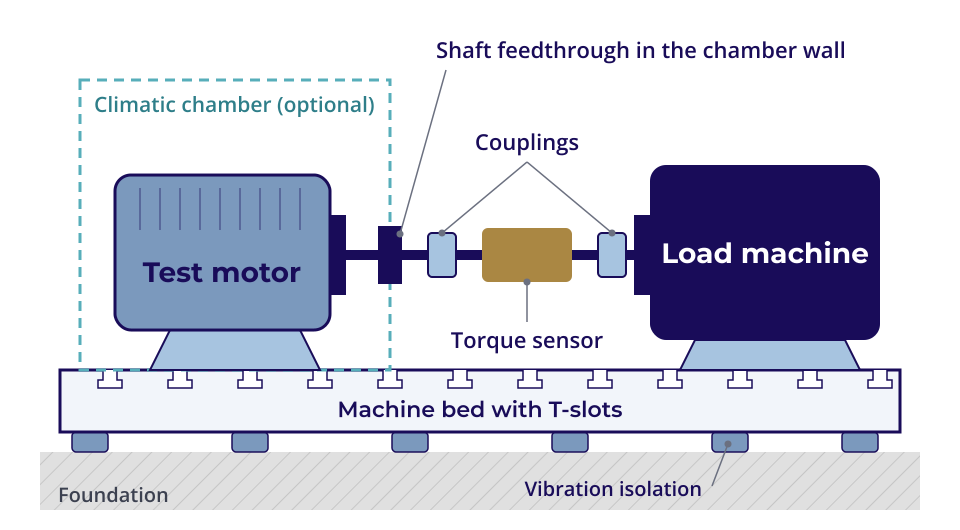
The machine bed carries DUT, shaft train and load machine. It determines how well the test stand absorbs vibration. At high speeds its natural frequency has to be well above the excitation from operation, otherwise resonances distort the measurement and stress bearings and couplings. Clamping plates with T-slots take different DUTs without rebuilding the bed.
Depending on requirements, cast iron, steel, mineral casting or hybrid designs come into question, isolated from the building by air springs or steel spring elements. Which substructure suits which test task is described in our knowledge article on test stand substructures.
Shaft train: adaptation, coupling and torque measurement
Between DUT and load machine sit the adapter flange, couplings and a torque transducer. The mechanical design depends heavily on the DUT. Car drive motors today spin up to about 20,000 rpm, new generations already above 30,000 rpm. Ship and rail drives, on the other hand, work at very high torques and much lower speeds. Bearings, couplings and transducer differ accordingly. The whole train is aligned and balanced. For high speeds we design it rotordynamically so that it runs below the first bending natural frequency.
If the shaft passes through the wall of a temperature chamber, the feedthrough needs its own solution for sealing and bearing. We have several proven designs, selected by speed and temperature range.
Load machine and back-to-back
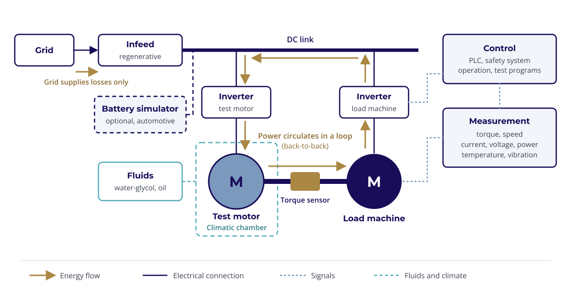
The load machine brakes or drives the DUT. For this it works in four-quadrant operation: motoring and generating in both directions. Drive profiles with acceleration and recuperation can be reproduced. The energy the DUT generates is fed back by the load machine through its inverter.
In a back-to-back test stand, two identical motors are mechanically coupled. One works as DUT, the other as load, and the roles can be swapped in software. If both inverters share a common DC link, the power circulates. Only the losses are drawn from the grid. For motors in the megawatt range this reduces the required grid connection and energy costs considerably. The prerequisite is two identical motors. For single DUTs, a dedicated load machine remains the solution. Our specialists bring experience from numerous back-to-back setups.
Inverter and battery simulation
The DUT is fed either by the customer's inverter, e.g. the vehicle's series inverter, or by a purchased industrial inverter that we integrate into the test stand. We size inverter and voltage level for the largest DUT. For good torque control the smallest motor must not be too small for the inverter: as a rule of thumb its rated current should not be below about one sixth of the inverter's rated current.
In the vehicle, the inverter is connected to the traction battery. On the test stand a regenerative DC source replaces the battery. This battery simulator sets voltage and internal resistance reproducibly, including states of charge and voltage dips that would hardly be repeatable with a real battery. Where no battery system has to be reproduced, as with many rail drives, a supply module feeds the DC link from the grid.
Climate chamber and media conditioning
For thermal tests the motor sits in a temperature chamber. A traction motor gives off a lot of heat under load, so the chamber alone cannot hold the temperature stable. Conditioned air from an external air handling unit is routed through the test cell so that the DUT is evenly surrounded. Chambers down to -40 °C are common; lower temperatures are possible on request. The chamber also needs feedthroughs for shaft, coolant hoses, measurement lines and motor cables. We supply suitable climate chambers through our environmental simulation line.
Motor and inverter are usually cooled with a water-glycol mixture, many new motors also with oil. Media conditioning brings these coolants to defined temperatures, pressures and flow rates so tests stay repeatable. It mixes cooled and heated medium through a control valve to the target temperature, with control accuracy better than 0.1 K. In cold tests oil becomes very viscous. The pumps have to circulate it reliably even at -40 °C. We design the conditioning for each test stand ourselves and integrate it to suit the installation, e.g. space-saving under the grating floor of the test cell.
Measurement technology
Measured are torque and speed at the shaft, currents, voltages and electrical power at motor and inverter, plus temperatures, pressures, flow rates and vibration. Efficiency requires a power analyzer that captures the pulse-width-modulated quantities at the inverter output accurately enough.
We select measurement technology independently of any vendor and bring all channels together in one database. Data from different systems do not have to be merged afterwards.
Safety
A large motor stores a lot of kinetic energy at high speed, plus high voltage and high currents. The safety concept includes burst protection and enclosure, emergency stop, standstill monitoring, access control to the test cell and protection of live parts. The basis is the European regulations that apply when the system is placed on the market.
Software
Automation and ready-made test programs
The software determines how efficiently a test stand works day to day. We program control and operation so that test sequences run automatically and limit values protect DUT and system. More: Test stand automation
In manual mode the operator sets setpoints such as speed, torque or DC link voltage directly, e.g. during commissioning or troubleshooting. In automatic mode every test has its own screen. The operator enters the parameters, loads a load profile, e.g. from an Excel sheet, and starts the test. Steps advance by time or by condition, e.g. once temperatures are constant. Setpoints and actual values are plotted during the test and saved.
Custom evaluations and standardized test procedures
Our test stand software supports custom test sequences and evaluations as well as standardized test procedures. For the standardized procedures we integrate proven software such as imx OMEGA from imx Solutions. It comes with around 15 test types plus motor management, monitoring and reporting. In active test types the motor is energized and loaded; in passive ones the load machine drags it unenergized. Examples:
- Characteristic curve measurement
- Torque, power, losses and efficiency, measured statically or dynamically, e.g. for data sheet and control strategy.
- Flux table
- Magnetic flux in d and q direction over many load points. Basis for efficiency and losses of permanent magnet synchronous motors.
- Torque ripple
- Torque fluctuations at constant speed, evaluated by magnitude and frequency.
- Operating temperatures
- Heating depending on usage profile, as a basis for continuous load capacity and service life.
- Generator voltage
- Induced voltage over rotor angle. Deviations point to faults in winding, magnets or air gap.
- Phase resistance and inductance
- Winding symmetry and angle-dependent inductance over one revolution.
- Cogging and drag torque
- Cogging torque at very slow drag, drag torque over speed, e.g. as an indicator of bearing damage or rubbing parts.
- Encoder test
- Comparison of the encoder signal with a reference encoder to detect angular offset between rotor and stator.
In addition, imx PI parameter identification determines motor parameters without a load machine.
Modernization
New build or retrofit
Not every new test task needs a new test stand. Machine bed, load machine and chamber of an existing motor test stand are often in good condition, while controls, inverter or measurement technology are outdated or insufficient for new DUTs. Then a retrofit pays off. We survey the existing system, check what can be reused and modernize selectively. Depending on the system's condition, savings of up to 50 percent and more compared with a new build are achievable. More: Retrofit and modernization
Alstom · Netphen service center · 2025/26
In Netphen, Alstom tests drive units from bogie overhauls. The existing drive test stand was designed for units with an integrated motor. For the Talent and Vectron platforms, whose drive units arrive without a motor, we extended it with a control cabinet containing a frequency inverter, braking resistor and its own PLC. One inverter supplies the auxiliary motors of both test fixtures alternately; the parameters switch automatically. Operation remained unchanged for the staff. The test stand is designed for around 1,100 drive units per year.
Approach
From requirements specification to commissioning
A test stand project starts with the test task, not with a parts list. If a complete specification is still missing, we develop it together: as a solution sketch in one to five days or as a vendor-neutral requirements specification. Then follow functional specification, design, construction, commissioning and acceptance.
Engineering, control technology, software and system integration are ours. Partners supply defined disciplines such as machine beds under our project responsibility.
FAQ
Frequently asked questions about traction motor test stands
A traction motor test stand is a test facility for electric drive motors in vehicles, trains, working machines and ships. The motor is coupled to a load machine on a machine bed and operated at defined speeds, loads and temperatures. Measured are torque, speed, electrical quantities and temperatures.
Yes. Both terms describe the electric motor that propels a vehicle. "Traction motor" is the common term in rail and e-mobility; "drive motor" or "e-motor" is often used for passenger cars.
Typical are characteristic curve and efficiency measurements, endurance runs in the duty types of EN 60034-1, thermal tests such as HTOE and PTCE, overspeed and short-circuit tests and end-of-line tests. Which of these are needed depends on whether testing takes place in development, in production or after repair.
HTOE stands for High Temperature Operating Endurance, an endurance run under load at high temperature. PTCE stands for Powered Thermal Cycling Endurance, an endurance run under load with cycling temperature. Both tests originate in automotive development and reproduce the thermal stress over the service life in compressed time.
In a back-to-back test stand two mechanically coupled, identical motors drive each other, one as DUT, one as load. If the inverters share a common DC link, the grid only has to cover the losses. This pays off above all at high power and when two identical motors are available anyway.
In the vehicle the traction battery supplies the inverter. On the test stand a battery simulator replaces it and sets voltage, internal resistance and state of charge reproducibly. Tests can be repeated at any battery voltage without charging, discharging or stressing a real battery.
Yes. The test stand then takes the complete drive unit instead of the motor, e.g. a rail drive of motor, gearbox and shaft, or an e-axle. Load machine, torque measurement and adaptation are designed for the output side, where speed is lower and torque higher.
In many cases, yes. We survey the existing system and check which parts can be reused, often the machine bed and mechanics. Controls, inverter, measurement technology and software are then renewed or supplemented selectively.
Talk to an engineer
Describe your device under test and test task. We get back to you with a first assessment of design, test procedures and the question of new build or retrofit.