HiL testing: why hardware-in-the-loop is indispensable today
This article was first published in German in GO>>ing magazine (issue 3/2025, pages 84–87). Here is the full English version. You can also download it as a PDF.
1. Introduction: why hardware-in-the-loop is indispensable today
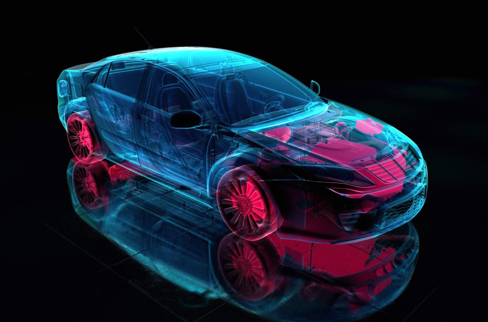
Developing mechatronic vehicle components keeps getting more complex. Software and hardware are growing closer together. Control units take on safety-critical tasks. Systems must work reliably under a wide range of environmental conditions. To meet these requirements, realistic tests in early development phases are essential. This is where hardware-in-the-loop (HiL) testing comes in. It lets you test components in a virtual but realistic environment: fast, safe and efficient. That is why HiL test stands are now an integral part of modern development processes.
2. What is a HiL test?
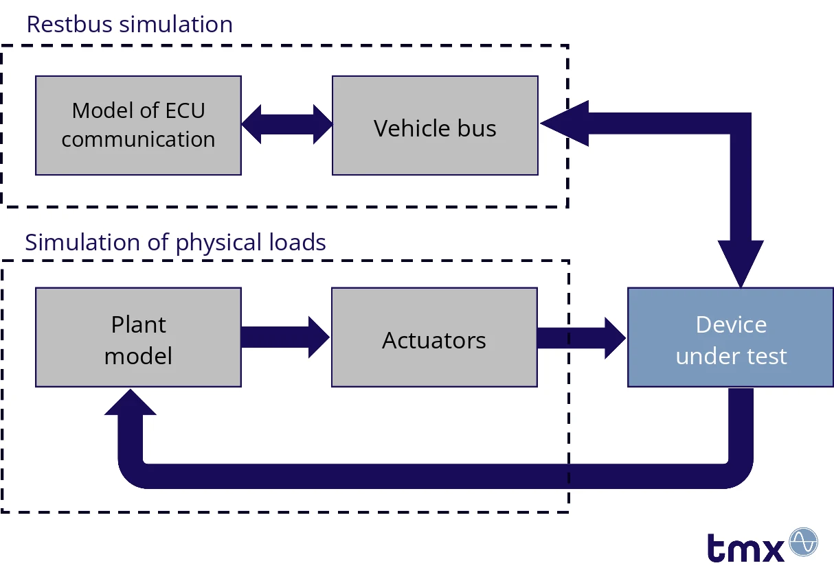
Hardware-in-the-loop is a test method that integrates real hardware into a simulation environment. The hardware can be a mechatronic component or assembly such as central locking, mirror adjustment, air conditioning or steering systems. The goal is to test the component’s behavior under realistic conditions without building the complete physical system. The device under test “believes” it is already operating in the real system, because all relevant signals, physical quantities and bus communication are simulated. This helps you detect errors early, shorten development times and improve system safety.
3. HiL test stands in detail
A HiL test stand connects real hardware with a digital model of the complete system. It reproduces mechanical influences such as forces, temperatures and vibrations as well as electronic signals and communication protocols. Real-time simulations make it possible to analyze how the device under test responds under dynamic conditions. Common bus systems such as CAN or LIN connect the control unit and the actuators. Specialized software platforms, for example based on MATLAB Simulink, Vector or dSPACE, model and control the system behavior in real time.
4. Typical applications
HiL test stands are used in many industries:
- Automotive: validation of electromechanical components such as power windows, seat adjusters or steering systems.
- Agricultural machinery: testing of gearboxes and hydraulic subsystems under dynamic loads and environmental conditions.
- Rail: testing of rail gearboxes, train doors or air conditioning systems under realistic operating profiles.
5. Requirements for modern HiL test stands
A modern HiL test stand must meet high requirements. The simulation software must be flexible and expandable, and the hardware must be robust and reliable. Real-time capability is especially critical: it is the only way to reproduce dynamic responses accurately. Expandability and modularity make it possible to integrate new control units, bus protocols or environmental simulations. The user interface must be intuitive and still be able to map and document complex test sequences.
6. Case study: HiL testing of a power window motor
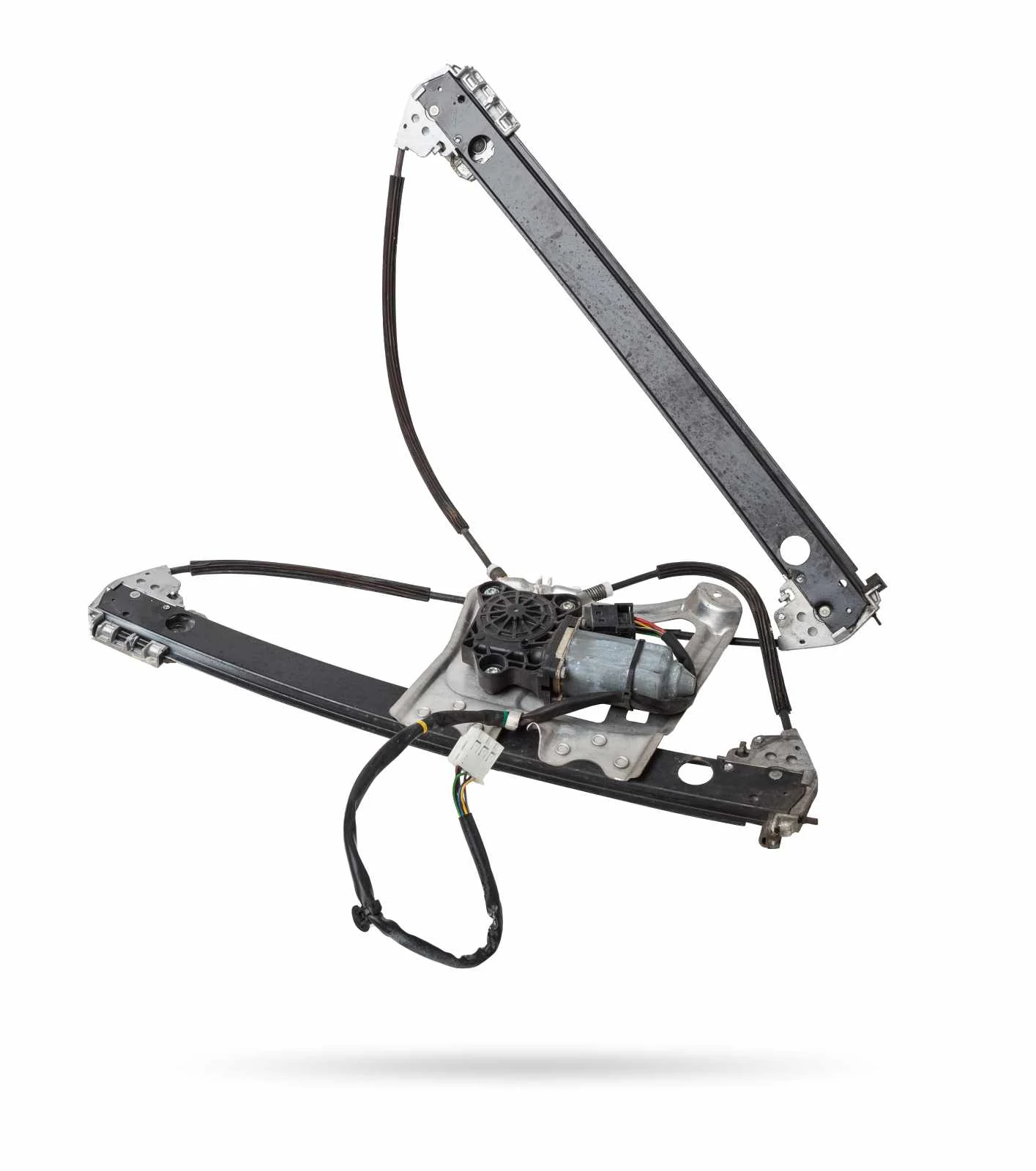
At first glance, a power window seems unspectacular. A closer look reveals considerable complexity. A modern power window combines mechanics, electronics, sensors, bus communication and safety-relevant functions. That makes it an ideal candidate for HiL testing.
The test is about more than whether the window moves up and down. It covers realistic loads, temperature behavior, communication with the control unit and intelligent functions such as anti-pinch protection or comfort operation.
Realistic simulation of mechanical loads
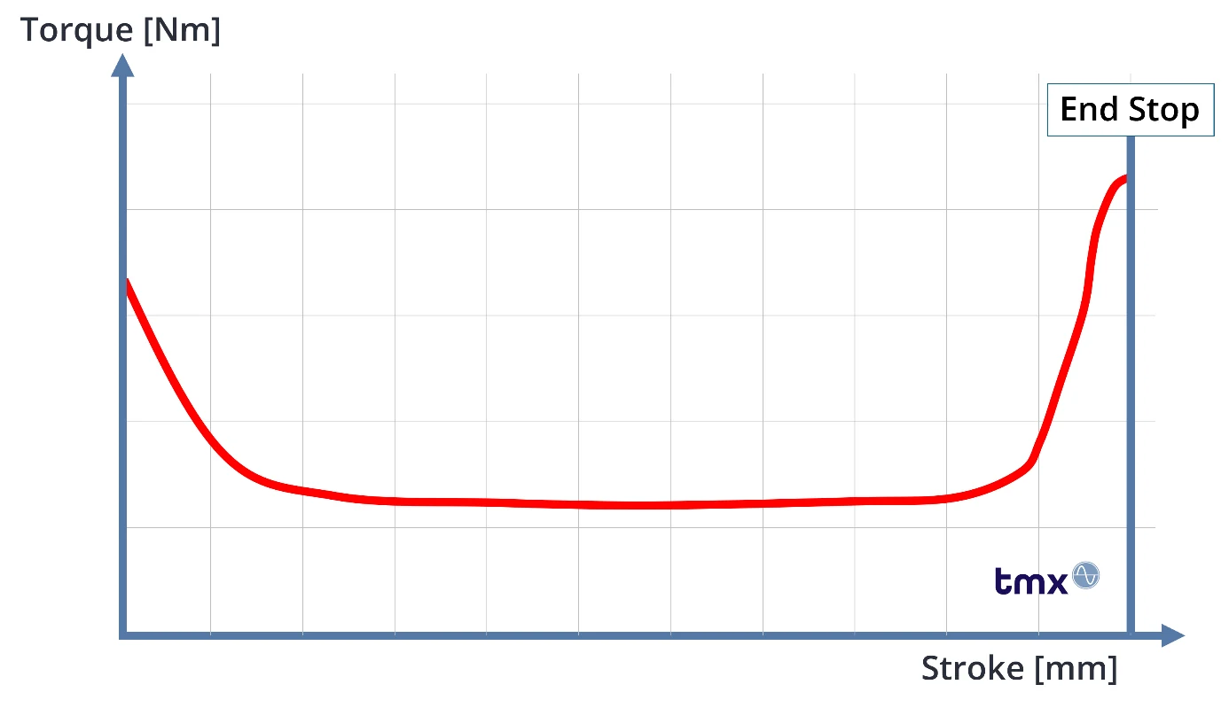
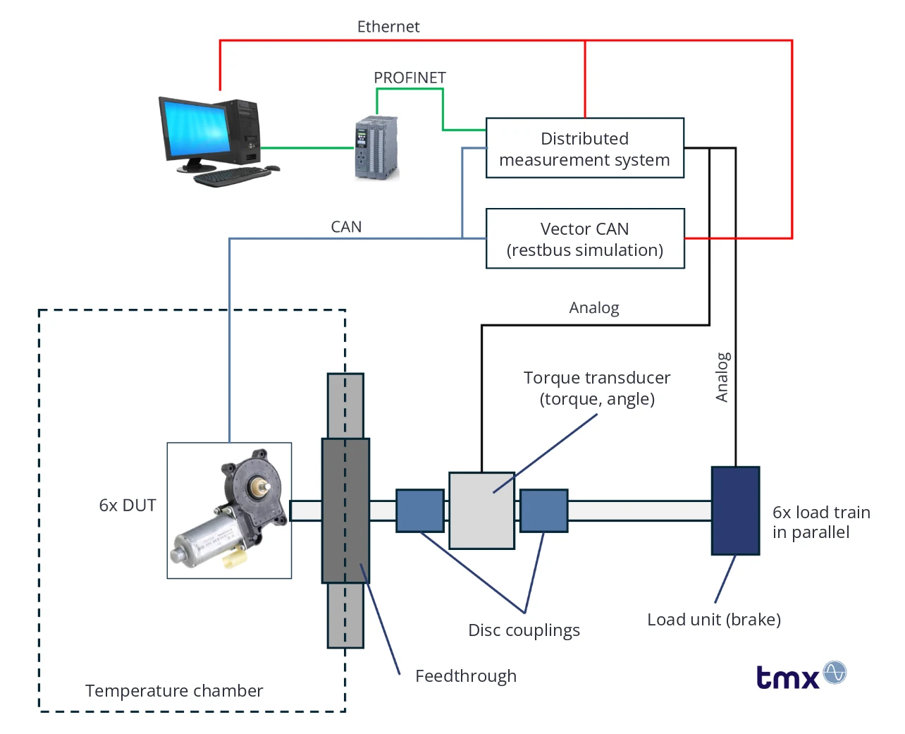
On the test stand, the power window motor is mounted on a mechanical test setup that operates it under realistic conditions. Friction forces that occur in the vehicle, for example from rubber seals or guides, are reproduced as load torques on the motor shaft. At the lower and upper end stops, the forces rise sharply, for example due to the curvature of the glass or the limit set by the frame. Simulating a typical stroke-force profile shows exactly how the load changes along the movement, for example when the window approaches the upper end stop or when a blockage occurs.
The test stand can even inject faults on purpose, such as jammed pulleys or blocked cable guides, to test how the system responds. This is a key step in validating comfort and safety functions.
Temperature behavior: from arctic to tropical
The power window must withstand extreme climatic conditions: from arctic −40 °C to over +100 °C caused by heat build-up. On the test stand, the motor is heated or cooled in a temperature chamber to study thermal effects on motor behavior. Current and voltage, torque, window stroke and motor temperature are measured in relation to the ambient temperature.
This shows how heat build-up from direct sunlight or frozen seals affects starting behavior, power output and current draw. By varying temperature and load torque in a targeted way, you can detect and assess thermally induced malfunctions, power loss or material fatigue early.
Control unit integration and bus communication
The power window is controlled by an electronic control unit (ECU) that communicates with the motor via field buses such as CAN or LIN. The test stand simulates the vehicle environment, including switches, door locking and comfort functions. It also triggers safety-relevant functions such as anti-pinch protection and analyzes how the system responds.
Data processing
Measurement data is acquired and evaluated in real time and fed back to the simulation models and control algorithms (closed loop). Fully coupling measurement, control and simulation creates a closed HiL system that is powerful, scalable and reproducible.
Custom HiL test stands
The benefits of HiL testing are clear: realistic tests in early development phases, lower risk of errors and faster time to market. To use this potential in full, you need test stands that match the specific application technically, functionally and economically.
Requirements, interfaces and tools differ significantly depending on the industry and the task. That is why some providers, such as TMX Solutions, focus on custom test stand concepts. With more than 20 years of experience in test stand construction and a deep understanding of measurement, control and automation technology, TMX develops individual solutions. They adapt flexibly to existing system landscapes and common tools such as MATLAB Simulink, NI VeriStand, dSPACE, ETAS INCA or Vector CANoe.
If you are looking for a custom solution for your test task, a vendor-independent partner like TMX can help you find the right test stand.
Authors: Nils Becker and Christian Perdok, TMX Solutions GmbH
TMX builds HiL test stands for your requirements
At TMX Solutions, we build custom HiL test stands whose mechanics and controls are tailored to your requirements. We work vendor-independently and support common tools such as MATLAB Simulink, dSPACE, CANoe and INCA. Our solutions are modular, scalable and proven in practice, from the first concept to commissioning.
Learn more on our page about HiL test stands.
Original publication and PDF
The German original appeared in the ePaper of GO>>ing magazine, pages 84–87. We would like to thank the GO>>ing editorial team for the professional collaboration.
YOUR NEXT STEP
Get in touch
We look forward to learning about your test and measurement tasks and developing solutions together that take your projects to the next level.