Test stand bases: which base frame fits which test task
When you design a test stand, the base is rarely where you start. The focus is on the device under test, drive power, and measurement technology. Yet once the test stand is running, you can hardly change the base frame without stopping operation. And it affects more than you might think at first.
Basics
Four factors a test stand base affects
- Measurement quality
- If the natural frequencies of the setup fall within the excitation range, they distort the measurement result.
- Noise at the workstation
- A frame that goes into resonance becomes audible, and rarely pleasantly so. Operators find unsteady noise especially wearing over a full shift, the kind that appears during run-up and fades again.
- Service life
- Continuous operation close to a resonance accelerates wear on bearings, bolted joints, and welds.
- Safety
- Setups with high rotational energy need a defined path for forces into the hall floor.
How much each of these four points matters depends on the test task. On a tire test stand that measures tire temperature during run-up, vibration barely affects the result. For operator noise exposure and for the life of the test stand, the same vibration matters a lot. On a traction motor test stand with NVH measurement, it is the other way around.
Terms
Base frame and foundation
Inquiries and requirements specifications often treat the base frame and foundation as one topic. Technically, they are two separate tasks. The frame, or machine bed, determines the natural frequencies of the setup itself. Stiffness, mass, geometry, and material damping are what count. A frame that is too soft or poorly shaped has its own vibration modes, no matter how the test stand is installed.
Foundation and vibration isolation, on the other hand, determine the coupling to the building. They keep vibration from traveling out of the test stand into the hall and, the other way around, keep ground vibration from disturbing the measurement.
In practice, this regularly leads to a misunderstanding: elastomer mounts, air springs, and machine feet act only on the coupling. They do not help against natural vibration of the setup. If a frame starts to ring at certain speeds, softer mounting will not fix it.
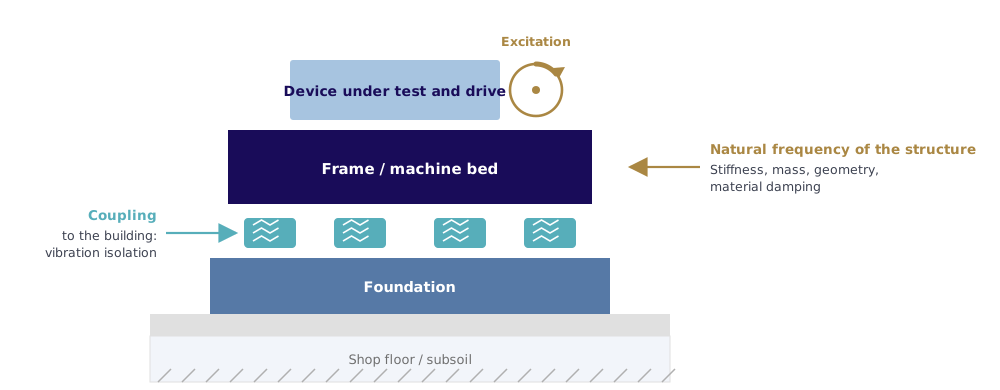
Frame and foundation act on two separate levels: the frame on the natural frequency of the setup, the isolation on the coupling to the building.
Selection
Test task and leading criterion
Everything hinges on one decision: does the natural frequency of the setup matter here or not? If it is secondary, you can choose from a wide range of materials. If you need a natural frequency above about 400 Hz, only a few options remain.
| Test task | Leading criterion | Secondary | Suitable classes |
|---|---|---|---|
| Lab setup with frequently changing configuration, small devices under test | Flexibility, changeover time | Natural frequency | Aluminum profile, aluminum profile with inset plate |
| Static and quasi-static tests, large setups | Cost-effectiveness, installation space | Natural frequency, damping | Welded steel frame |
| High-precision measurement setup with low dynamics (e.g., coordinate measurement) | Flatness, temperature stability | Freedom of geometry | Natural granite |
| Tire endurance testing with wheel load application | Noise, service life | Effect on measured values | Steel frame with mineral filling, solid mineral casting |
| Gearbox endurance testing in multi-shift operation | Service life, workplace | Flatness | Filled steel frame, solid mineral casting, T-slot field |
| Traction motor / e-drive up to 30,000 rpm with NVH measurement | Measurement quality (400–500 Hz) | Changeover flexibility | Solid mineral casting (high modulus), natural granite for simple geometry |
| Tests with deliberately applied unbalance | Measurement quality, safety | Cost | Solid mineral casting |
| Test field with changing heavy setups | Variability, repeatability | Natural frequency per setup | T-slot field on steel, hybrid, or mineral casting base |
These classes form a progression, from the flexible but vibration-sensitive solution to the solid component for high speeds. Each has a range where it is the economically right choice.
Designs
The five base classes
Aluminum profile systems
The most common base frame for a test stand is built from aluminum profiles, which many people know as item profiles (in the US often as 80/20). Extruded slotted profiles connect via T-nuts and brackets into almost any structure. Add accessories for nearly every purpose: brackets, casters, doors, cable ducts, panels. The system is sometimes called Lego for engineers, and the comparison fits.
For a lab test stand, this is often the right choice. The setup goes up fast, can be rebuilt the next day, and the entry cost is low. If you regularly take on different devices under test, you save more time than a stiffer design would ever pay back.
In terms of vibration, however, a profile setup is not a good partner. The T-nut joints rely on friction and are therefore vibration-critical, and the open structure barely damps. As soon as something rotates or is loaded dynamically, you notice it. If you want to stay with the profile system anyway, set a solid plate into the frame as the clamping surface: the frame carries the load, the plate takes the forces.
Typical uses are functional and first article testing, lab test stands, and secondary structures such as panels, operator consoles, and cable routing.
Welded steel frame
As the setup gets larger and heavier, aluminum profiles reach their limit. The next step is usually a welded steel frame made from plate, square tubing, and pipe, built to drawing as a one-off. Most test stands start with this design, and for many tasks it is the right one.
The reason is simple: for a batch size of one, there is hardly anything more cost-effective, even at large dimensions. You can place connection points, fixtures, and openings freely, and if something is missing later, you rework it. No other material offers this freedom.
The catch is flat plate panels. They behave like membranes and have their own, often surprisingly low, natural frequencies. A variable-speed test run will almost inevitably hit one of them.
If you use a welded steel frame for a test stand running up to 20,000 rpm, the run-up typically passes through several resonances. The side panels act as membranes and produce a clearly audible tone at certain frequencies. A natural granite base reliably solves this in this speed class, as long as the device under test is well balanced and precisely aligned.
Natural granite
When a steel frame reaches its limit, the classic route leads to stone. Natural hard stone, usually granite, is sawn from the block and lapped into plates, beams, angles, and solid blocks. The material stays dimensionally stable for decades, damps well, and responds slowly to temperature changes. With careful grinding, it reaches flatness in the single-digit micrometer range. It does not corrode and is non-magnetic. That is why it has long been standard in metrology.
Only simple geometries are cost-effective. Complex shapes are built from several parts whose joint surfaces are ground, bonded, and bolted, and the effort rises quickly. Inserts cannot be cast in; they can only be bonded or bolted on afterward. A T-slot field directly in the stone is not economical; it would have to be made separately and mounted on top.
What matters is less the speed than the excitation. Natural granite works well at high speeds as long as excitation stays low, that is, with well-balanced and precisely aligned devices under test.
Traditionally, natural granite is used in coordinate metrology, for runout and form testing, and for precision measuring tables. It also suits high-speed test stands, as long as the geometry stays simple and no inserts are needed.
Welded steel frame with mineral filling
You can solve the damping problem of the steel frame without giving up the design. Fill the welded structure with a mineral material. The steel skin still carries the load and provides the machinable functional surfaces; the filling adds damping and mass. For a test stand where something turns steadily and fast, this is often the decisive step.
Compared with a plain steel structure, damping rises significantly, and the connection surfaces stay millable. The filling density also lets you set the component weight within wide limits. That matters when the hall crane has limited capacity or when the component itself moves, such as a drum or a load carriage. Very large dimensions are possible, too.
In return, the natural frequency is harder to predict than with a solid cast component. The highest modulus values of solid mineral casting materials cannot be reached as a filling; stiffness is increased through reinforcement and plate thickness instead.
This design is used for rotating and dynamically loaded devices under test in the medium speed range, on tire and roller test stands, and for moving assemblies such as drums and load carriages.
Solid mineral casting
At the top end, the steel structure goes away entirely. The component is cast as a whole in a mold, leaving solid material. Steel plates, threaded inserts, conduits, and mounting rails are cast in, and the raw body then goes to precision machining. For heavy and large setups, such as a tire test stand with a drum, this is the most consistent solution.
Among castable materials, this design reaches the highest stiffness, combined with high damping and wide freedom of geometry. Because the component is homogeneous, its natural frequency can be calculated reliably, which is not possible with welded designs. Media lines for coolant, electrical cables, or compressed air can be integrated directly, so no lines need to run around the outside of the test stand.
There are two binder systems to distinguish. Resin-bonded mineral casting, also called polymer concrete or epoxy granite, reaches a modulus of elasticity of about 35,000 to 40,000 N/mm². Cement-bonded ultra-high-strength mineral casting comes in two grades, at about 45,000 N/mm² and 80,000 N/mm². The higher grade is comparable to natural granite in its mechanical properties but makes better use of cast-in inserts.
An e-drive running at 25,000 to 30,000 rpm needs a test stand with a natural frequency of 400 to 500 Hz. The value follows directly from the speed: 30,000 rpm equals 500 Hz, 25,000 rpm about 417 Hz. The natural frequency of the setup must lie above the highest rotational frequency so that no interfering frequencies enter the measurement across the entire run-up curve. If the calculated value is not enough, the overall height is the most effective lever, because it enters the area moment of inertia to the third power. If height is limited, thick steel plates on the top and bottom help: with their high modulus, they sit far from the neutral axis.
For one-off production, mold costs dominate, because the mold is usually not reused after casting. The material can be ground but not milled. All milled functional surfaces are on cast-in steel parts.
Typical applications are high-speed drive test stands, test stands with deliberately applied unbalance, setups with complex geometry and integrated media routing, and test stands where the customer's setup is not yet fixed.
Properties
Material properties for machine beds and test stand frames
The following values indicate orders of magnitude. Properties of mineral materials depend on mix and manufacturer; for a specific design, the supplier's data apply.
| Material class | Modulus of elasticity (N/mm²) | Density (kg/m³) | Damping | Machining / inserts |
|---|---|---|---|---|
| Aluminum profile | approx. 70,000 | approx. 2,700 | low | T-nuts, can be changed any time |
| Steel (welded) | approx. 210,000 | approx. 7,850 | very low | freely millable and weldable |
| Natural granite | approx. 70,000–100,000 | approx. 2,700–3,000 | high | bonded or bolted on only |
| Steel frame with mineral filling | structure dominated by steel | adjustable via filling | significantly higher than steel | functional surfaces millable |
| Resin-bonded mineral casting | approx. 35,000–40,000 | approx. 2,300–2,400 | high | inserts can be cast in |
| Cement-bonded mineral casting, standard grade | approx. 45,000 | approx. 2,500 | high | inserts can be cast in |
| Cement-bonded mineral casting, high grade | approx. 80,000 | approx. 2,500 | high | inserts can be cast in |
Accuracy requirements are often where you can save money. Machine tool building calls for flatness down to a few micrometers. Test stand building needs much coarser tolerances, on the order of 0.02 to 0.04 mm over two to three meters. If you apply machine tool standards to a test stand without question, you pay for precision that does nothing for the test task.
Clamping
Clamping plates and T-slot fields
A T-slot field is not a separate base class but an addition. It creates a variable clamping surface on which test setups can be mounted, moved, and rebuilt without touching the base structure.
In practice, repeatability is what matters. With dowel pins, setups can be reproduced to a tenth of a millimeter. That counts wherever the same device under test is measured in series or the same setup is measured again after a changeover.
The range extends from a small plate set into an aluminum profile frame to the continuous clamping field of a test bay carrying complete gearbox test stands. On mineral bases, the slots are usually not milled from solid material but made with cast-in steel plates or prefabricated slot rails. The rails protrude a few millimeters above the cast surface so the milling head does not touch the mineral material during machining. Slots milled from solid would cost significantly more.
The same applies to accuracy as above: for T-slot clamping plates, flatness of 0.03 to 0.05 mm is usually enough. Relevant German standards are DIN 650 for slot dimensions and DIN 55201 and DIN 55202 for clamping plates. Combining a T-slot field with natural granite does not make sense, because the slot field would have to be made separately and mounted on top.
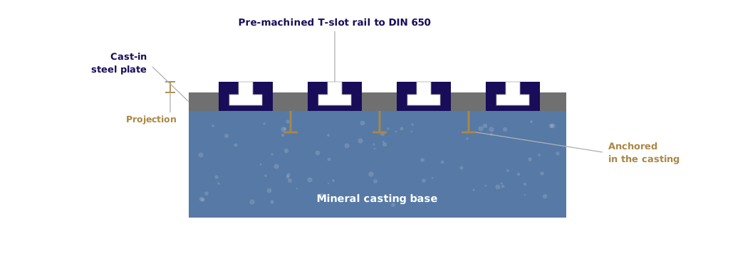
Slot rails on a mineral base, schematic.
Installation
Vibration isolation and foundation
Depending on the situation, isolation serves one of two goals. Source isolation keeps vibration from the test stand out of the building and away from neighboring workstations. Receiver isolation works the other way: ground vibration from the surroundings must not disturb the measurement.
Isolation only works when the excitation frequency lies well above the natural frequency of the spring-mass system. As a guide, f / f₀ > √2. Below this ratio, vibration is amplified, not reduced. More damping lowers the resonance peak but worsens isolation above this limit.
The common approaches differ mainly in the natural frequency they can reach. Leveling mounts and machine shoes cover simple installations, elastomer mounts the middle range, steel springs lower frequencies, and air spring systems the lowest values for highly sensitive setups. An inertia block as a separate mass in the building structure is used when high forces must be transferred.
If a test table sits on air springs, all connections must be flexible. A rigid line or a firmly bolted attachment bridges the isolation and sooner or later breaks, because it has to absorb the relative movement.
Relevant guidelines are VDI 2038 on the serviceability of structures under dynamic loads and ISO 10816 on the evaluation of machine vibration.
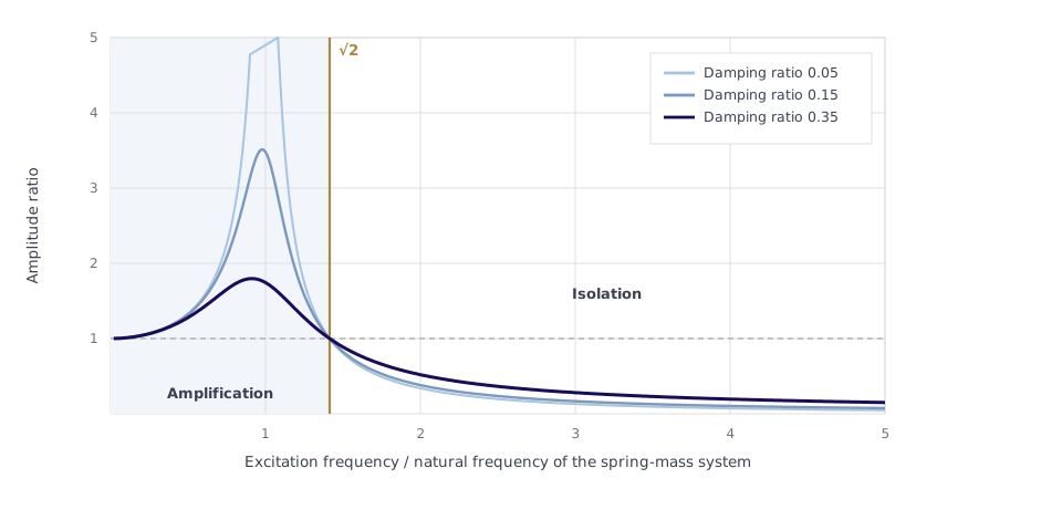
Transmissibility for three damping ratios. Isolation only starts to the right of the root-two line.
From practice
Common design mistakes
The following points come from our own projects and from modernization projects in which we reworked existing test stands.
- The operating speed range is checked against a single natural frequency instead of the entire run-up curve. The run-up then hits resonances that would not show in continuous operation.
- Excitation is defined only by the device under test. Auxiliary units, couplings, and load machines add their own orders that are missing from the design.
- Vibration isolation is planned as a fix for natural vibration of the frame. It only acts on the coupling to the building.
- In multi-part designs, tolerances add up across the joints. The complete setup ends up less accurate than the individual part.
- The transport route comes in too late. Door widths, missing hall cranes, and whether a part can be moved by forklift regularly decide the maximum possible part size.
- Ergonomics at the finished test stand are overlooked. Protruding foot plates and bolted joints are tripping hazards; recessed connection plates with a smooth front edge avoid this.
Questions and answers
FAQ
What is the difference between a machine bed and a foundation?
The machine bed, or frame, determines the natural frequencies of the test setup itself. Foundation and vibration isolation determine how the setup is coupled to the building. One cannot replace the other.
Why doesn't vibration isolation help against natural vibration?
Elastomer mounts, steel springs, and air springs act between the setup and the floor. They affect what is transmitted into the building but do not change the stiffness or mass distribution of the frame. If a sheet metal wall vibrates at a certain frequency, it does so on any mounting.
How high does the natural frequency of a test stand need to be?
It should lie above the highest excitation that occurs in operation, including the entire run-up curve. For electric drives running up to about 30,000 rpm, the target is 400 to 500 Hz.
When is a welded steel frame enough?
For static and slow-moving tests and for large setups without relevant speed excitation, it is usually the most cost-effective solution. It becomes critical once you run at variable speed and flat plate panels can act as membranes.
Which material does a high-speed test stand need?
If you need a natural frequency above about 400 Hz, the main options are natural granite and high-grade solid mineral casting. For complex geometry, or when media lines and clamping plates need to be integrated, mineral casting has the edge.
Can a T-slot field be combined with any base?
It is common with aluminum profile frames, steel frames, filled steel structures, and mineral casting. With natural granite, it is not cost-effective, because the slot field would have to be made separately and mounted on top.
How accurate does a test stand base need to be?
Much less accurate than is usual in machine tool building. For most test tasks, flatness of 0.02 to 0.04 mm over two to three meters is enough; for T-slot clamping plates, 0.03 to 0.05 mm.
Bases in a test stand project
TMX Solutions designs and builds test stands from concept to commissioning. Our focus is on measurement, control, and automation. We select the base for each project and work with specialized manufacturers.
This has a practical advantage. Because we do not sell a material of our own, the choice depends only on the test task. For a lab test stand, an aluminum profile frame can be the right decision, while the same requirement at higher speed calls for a solid base. In both cases, we are responsible for the test result.
By the way: when modernizing existing test stands, the existing base is often the limiting factor. In several projects, including tire test stands, we assessed existing frames and decided which assemblies could be kept and which had to be replaced.
Standards
- DIN 650 – T-slots, dimensions
- DIN 55201 and DIN 55202 – Clamping plates and their T-slots
- DIN 876 – Flatness of measuring and clamping surfaces
- VDI 2038 – Serviceability of structures under dynamic loads
- ISO 10816 – Evaluation of machine vibration
Find the right base for your test stand
We check which criterion leads for your test task and select the right base, vendor-independent.