Brake distance measurement on rail vehicles: methods compared
Wheel encoders, GNSS, radar, inertial sensors, and optical sensors all measure the same quantity, but they don't measure the same thing. Why braking is exactly the load case where the methods differ.
What a brake distance test actually measures
A brake distance test records the stopping distance, i.e., the distance from brake application to standstill, and calculates the mean deceleration from it. Both are results, not measured quantities.
The actual measured quantity is the vehicle's speed over ground as a function of time. Distance and deceleration are derived from it. This is where the quality of a brake distance measurement is decided: a method is only as good as its picture of the true speed over ground during braking. Not while the vehicle is coasting, but during the few seconds of maximum deceleration.
There is a second requirement that is often underestimated: the start of braking must be captured unambiguously and repeatably. A method that measures speed very accurately but only roughly knows when braking started still produces a useless brake distance. The only reliable solution is an electrical brake trigger that starts the measurement in sync with the brake command. Not the speed curve, and certainly not the operator's perception.
The actual measured quantity is speed over ground as a function of time. Stopping distance and mean deceleration are results, not measured quantities.
Why slip is the critical error source
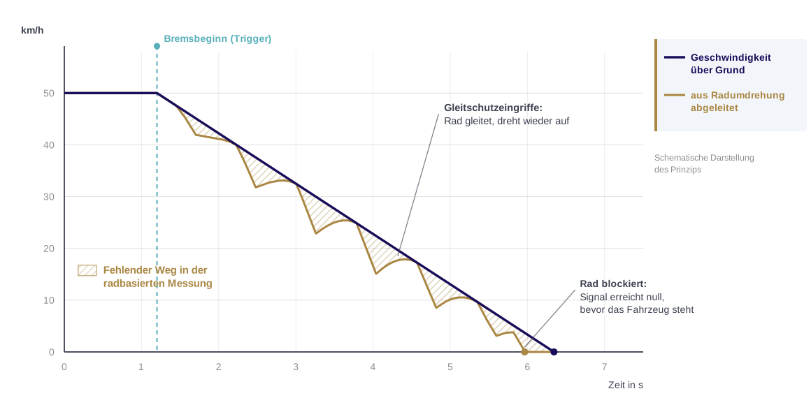
Brake testing happens under the worst possible conditions for wheel-based measurement. Under heavy deceleration, especially emergency braking, wheel-rail adhesion is used up to its limit. Wheels can slide and, in extreme cases, lock. The wheel's circumferential speed is then lower than the actual vehicle speed; the difference is slip.
For wheel-based distance measurement, this means the distance traveled is measured too short, and the brake distance looks better than it is. On wet or contaminated rail, with leaves on the track or frost, the effect gets bigger, exactly when braking performance is already critical.
Vehicles counter this with wheel slide protection (WSP). Electronic WSP detects speed drops on individual wheelsets and modulates brake pressure to prevent lockup. For the measurement, this creates a fundamental problem: WSP usually gets its actual speed from the same wheel encoders that feed the distance measurement. The measured quantity is influenced by a control loop that uses it as its own input. If you determine brake distance this way, you are not measuring independently of the device under test but from inside it.
The key question
Does the method measure speed over ground, or does it derive it from wheel rotation?
The methods in detail
Track marker and tape measure
The oldest method is still in use: the operator applies the brake at a track marker, and the distance between the marker and the front of the vehicle is measured afterward.
It needs no instrumentation and is easy to understand. But it is hardly repeatable. The start of braking depends on the operator's visual judgment and reaction time, the initial speed is read off the vehicle's speedometer, and the result is a single number with no speed curve. It tells you nothing about the deceleration profile, brake response, or the behavior of individual brake types. As documentation that has to hold up with the regulator or in a dispute, it is a weak basis.
Wheel-based distance measurement with encoders
On-board systems calculate distance traveled from wheel rotation. A wheel encoder, wheel sensor, or pulse generator delivers a number of pulses per revolution; multiplied by the wheel circumference, this gives distance.
The method is already available on almost every modern vehicle, requires no extra mounting, and delivers a continuous signal. But it has three systematic weaknesses, and all three come together during braking:
- Slip:
When wheels slide or lock, the measured speed deviates from the actual speed, and always downward: the brake distance appears shorter than it is. A Siemens study of measurement data from German ICE trainsets (Palmer and Nourani-Vatani, 2018) found that encoders, usually mounted on powered and braked wheelsets, tend to slip precisely during acceleration and braking, which is the measurement window of a brake test. - Wheel circumference:
The conversion assumes a known wheel diameter. It changes with mileage through wear and reprofiling, and also with temperature. The stored value has to be maintained; if it isn't, the derived speed is permanently wrong. - Traceability:
For an on-board system designed mainly for operation and control, there is often no record of regular, independent calibration of the measurement chain. That makes it hard to prove the measurement uncertainty behind the documented brake distance.
The wheel circumference error can be quantified. Tram wheels are typically installed new at a 600 mm running circle diameter and retired at 520 mm. A 3 mm loss in radius is about 1 percent, which shows up as about 20 cm on a 20 m brake distance.
In practice, the stored value is updated at wheelset inspection and reprofiling, so the error does not grow over the entire wear range. It stays limited to the wear since the last update, plus the accuracy with which the diameter was measured and entered at the time. That still does not give you a reliable figure for the remaining measurement error.
And there is the point made above: the vehicle tests itself with its own sensors.
The error is not the same on every wheelset. How much slip matters depends on where the encoder sits. Some vehicle designs use a non-powered, unbraked trailer wheelset as a reference. For brake testing, this raises a question that has to be answered for each vehicle type: does this wheelset stay unbraked in the brake type under test? If it is braked too, the slip-free reference is gone in exactly the load case the brake test is about.
What WSP leaves in the signal: When WSP intervenes during braking, it modulates brake pressure and lets the affected wheelsets spin back up. The recorded speed curve then shows dips and jumps that do not reflect vehicle motion but a control response (see the diagram at the top of this article). A method that measures speed over ground shows the true curve at the same point, which makes the WSP intervention visible in the first place.
GNSS (GPS, Galileo)
GNSS-based methods determine position before and after braking, and some also record the speed curve. The advantage is obvious: the measurement is independent of the wheel and therefore slip-free.
The limitations, however, are significant and, in urban rail, built into the environment. Tunnels, cuts, bridges, overhead contact line equipment, vegetation along the track, and dense buildings cause signal loss or multipath. The Siemens study mentioned above explicitly rates GNSS as particularly unreliable in the rail environment; in the mainline runs it evaluated, the signal dropped out several times, for up to several minutes. An urban tram network packs these disturbances into a much shorter distance.
On top of that, the antenna should sit on the vehicle roof for usable reception. That is only possible with the overhead line de-energized and makes the test procedure longer.
Even with a clear view of the sky, two weaknesses remain. The first is dynamic: GNSS speeds are usually filtered before output and can overshoot the actual value under abrupt deceleration before settling; latency is also higher and more variable than with direct-measuring methods. That is a drawback when determining the moment the vehicle drops below a defined speed.
The second is time resolution: typical GNSS receivers output position and speed at 1 to 20 Hz. At 20 Hz and 50 km/h (31 mph), the vehicle travels 0.7 m between two readings; at 5 Hz, almost 3 m. Brake application and standstill can only be interpolated, not measured, and both go directly into the brake distance. Direct-measuring methods are orders of magnitude finer here.
In everyday workshop use, there is also a practical hurdle: GNSS systems need a satellite fix before the first measurement and, depending on the system, a run-in distance. Both take time, and that time adds up across a vehicle fleet.
Radar and Doppler sensors
Doppler sensors aim microwaves at the track bed at an angle and evaluate the frequency shift of the reflected signal. They measure speed relative to the ground and are therefore slip-free. That makes Doppler radar the first method in this list that avoids both basic problems at once: it relies neither on wheel rotation nor on satellite reception. Accordingly, the technology is well established on rail vehicles, rugged, and relatively inexpensive. For brake testing, three points matter.
Mounting geometry acts as a scale error
A Doppler sensor only captures the speed component along the beam. Because the beam is tilted by design, typically between 30° and 45°, a misalignment of just one degree changes the speed reading by about one percent. Since distance comes from integration, that means one meter of error over a 100 m brake distance. On permanently installed sensors, the alignment is set once; on a mobile test instrument, it is set again with every installation. The market itself shows that this matters: rail Doppler radar sensors are offered with an optional inertial measurement unit whose stated purpose is to correct angular errors.
Availability depends on the track surface
Ballasted track, slab track, grass track, and paved sections reflect differently, and in a mature urban network the track type changes within a single test run. On snow- or ice-covered track, rail radar sensors are documented to work unreliably. Manufacturers address this too: one established rail sensor is available in a housing with a protective hood that, according to the manufacturer, improves availability in winter and protects against stone impact.
Near standstill, the signal gets small
As speed drops, so does the Doppler frequency, right where the stopping distance ends. The patent literature shows that this is a real limit of the method: there are techniques whose stated purpose is to extend the measuring range of such sensors toward standstill.
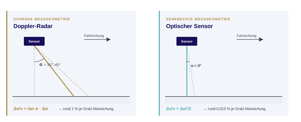
There is a design countermeasure against angle sensitivity: a Janus antenna radiates two symmetrical beams, one forward and one backward. If the sensor tilts, the Doppler frequency of one beam rises and the other falls; the average stays close to the untilted value. Sensors with this type of antenna are much less sensitive to tilt. Not every device uses the principle, however, and it compensates for pitch in the direction of travel, not for rotation about the vertical axis.
As one of several signals in a permanently installed odometry system, Doppler radar is proven. As the only reference of a mobile test system, it brings three error sources: mounting geometry, reflection dependence, and the near-standstill range. In the result, they can no longer be separated.
Inertial sensors
An inertial measurement unit (IMU) consists of accelerometers and gyroscopes. The accelerometers capture the vehicle's acceleration, the gyroscopes its orientation in space. Only the combination tells you in which direction to integrate and which part of the signal is due to gravity. Speed and distance result from single and double integration.
Inertial sensors are highly dynamic and need no contact with the ground. They work in tunnels as well as in the open and are independent of weather and track type. That makes them attractive for brake testing in principle, because they cleanly resolve the steep rise in deceleration when the brake engages.
Their weakness lies in the method itself. Acceleration signals are subject to drift and offset. Integration does not cancel these errors; it adds them up. A small constant offset grows linearly in speed and quadratically in distance over the measurement time. Without an independent reference, inertial sensors are therefore unsuitable for absolute distance measurement. As a complement, however, they are extremely capable.
Optical-only distance measurement
Optical sensors capture the texture of the surface under the vehicle and derive relative motion from it. In the spatial filter method, the illuminated surface is imaged through telecentric optics onto a grating-shaped photodiode array; the resulting spatial frequency is proportional to speed. The measurement is non-contact, slip-free, and requires no integration.
The method does have a signal characteristic that matters in practice: the amplitude depends on the reflectivity of the surface and varies widely. If the usable information falls below a threshold, for example on surfaces with very little texture or when kicked-up ballast briefly crosses the beam path, the signal drops out and then jumps back to the real value. On its own, optical-only measurement is accurate but not continuously fail-safe.
Optical-inertial sensor fusion
The approach TMX uses in the BrakeTest system combines both principles in one sensor. The optical spatial filter method provides the long-term stable, directly measured speed over ground. An integrated IMU provides the highly dynamic signal at a high output rate. The optics support the IMU and keep its drift out of the integration; the IMU in turn supports the optics and bridges short signal dropouts instead of passing them on as speed jumps. The result is a low-noise, highly dynamic signal that needs no post-filtering.
The geometry follows the same cosine relationship as the Doppler method, only at the other end of the curve. The optical sensor is mounted perpendicular to the surface and works at the peak of the function, where its sensitivity to angular deviation approaches zero. The telecentric optics provide tolerance for variations in mounting height. Together, these are the reasons such a sensor can be mounted repeatably as a mobile test instrument.
Distance is also formed in a fundamentally different way. In the spatial filter method, each signal period corresponds to a fixed distance increment; distance results from counting periods, not from integrating speed over time. A systematic scale error still acts proportionally, though, which is why calibrating the sensor on a roller test stand is not a formality but a prerequisite for a reliable distance value.
Near standstill, too, fusion plays to its strength. Every method that derives speed from a frequency works with a shrinking signal there. The inertial component is not critical in exactly this range: over the last few meters to standstill, the measurement time is so short that drift does not matter.
For the OMS 4, the manufacturer Sensoric Solutions specifies a speed measurement non-linearity below ±0.1 % FS. The sensor resolves the brake response as well as the short deceleration dips during WSP interventions that slower measurements average out.
Three properties are decisive for brake testing:
- Speed is measured over ground. Sliding or locked wheels, WSP interventions, and a changed wheel diameter do not affect the result. No calibration to wheel circumference is needed.
- The measurement is direct, not derived. There is no integration and no back-calculation from position differences. Latency is low and constant, which directly matters for determining brake application and the moment of standstill.
- The sensor works independently of the vehicle's systems. The measurement chain is separate from the device under test and can be calibrated as a closed system, on request in an ISO/IEC 17025 accredited laboratory. The result is traceable and holds up with the regulator or in a dispute.
Methods compared
| Method | Measured quantity | Slip-free | Main risk | Suitability |
|---|---|---|---|---|
| Track marker + tape measure | Distance (single value) | yes | Brake application not repeatable, no curve | low |
| Wheel encoder | Wheel rotation → distance | no | Slip during braking, wheel circumference drift, WSP feedback | limited |
| GNSS | Position → distance/speed | yes | Signal blockage, multipath, filter latency, low output rate | limited |
| Radar / Doppler | Speed over ground → integration | yes | Angle sensitivity, reflection dependence, near-standstill range | medium |
| Inertial only | Acceleration → integration | yes | Drift and offset accumulate, tilt errors | low |
| Optical only | Speed over ground | yes | Signal dropouts on weak reflection | high |
| Optical-inertial (fusion) | Distance and speed over ground, inertially supported | yes | Mounting point, scale factor calibration | high |
What to look for
Independence from the wheel
Any method that derives speed from wheel rotation measures systematically too favorably during braking. For a test meant to prove braking performance, that is the wrong direction of error.
Independence from the device under test
A measurement based on the sensors of the vehicle under test cannot reveal errors in those sensors. Especially for evidence after an accident, a separate, calibrated measurement chain is the more robust approach.
Availability on the real track
A method that is accurate in the lab but fails under trees, between tall buildings, in snow, or on changing track surfaces costs time every day. The question is not how accurately a method measures under ideal conditions, but how often you get ideal conditions.
Complete documentation
A single brake distance value is not enough if test scope and result have to be documented in a verifiable way. You need the speed curve, a clearly defined start of braking, the assigned brake type, and a test report that cannot be changed afterward.
The TMX BrakeTest system
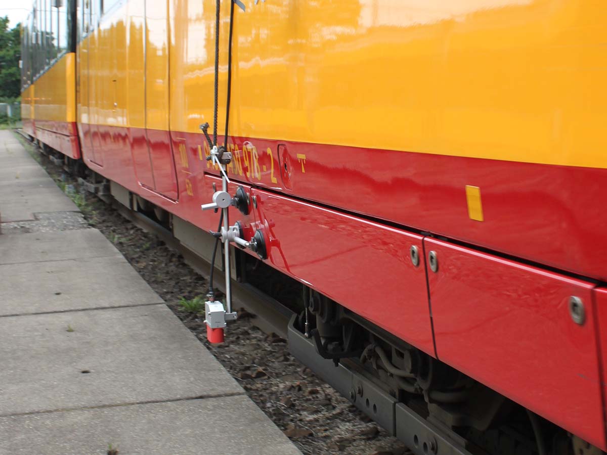
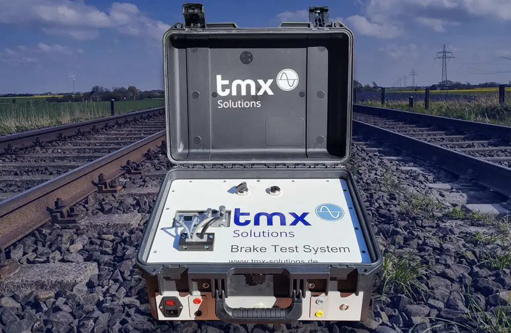
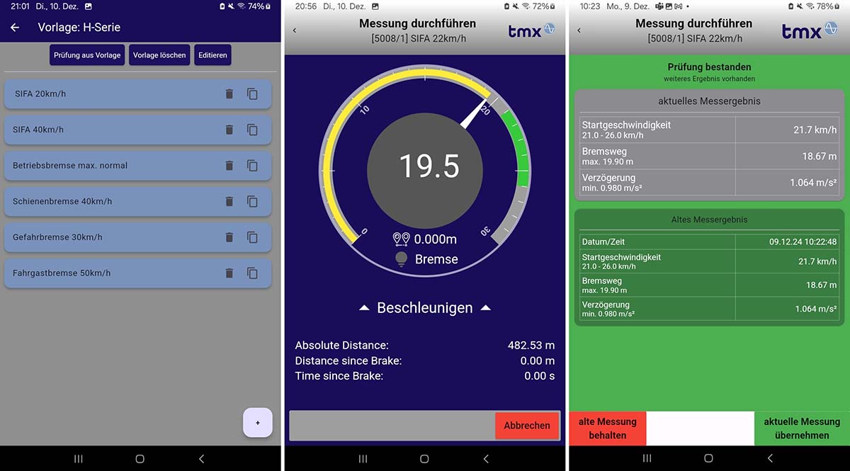
The TMX BrakeTest system puts these criteria into a mobile measurement system. It consists of the optical-inertial OMS 4 sensor from Sensoric Solutions, an electrical brake trigger for synchronized measurement start, rugged data acquisition in a portable case, and the TMX BrakeTestApp for operation on a tablet or smartphone.
In the app, you set up vehicles with fleet numbers, store limits, and define test sequences: from the complete brake test under the applicable national regulations to tests of individual brake types. During the measurement, the live display shows the speed range; the result is available right after braking. The final step is a tamper-proof PDF test report.
See how this works in a transit operator's daily routine in the Zurich Public Transport case study. Standards, intervals, and test procedure are summarized in the article Braking distance measurement on trams.
TMX BrakeTest system
Mobile measurement system for brake testing on rail vehicles, with optical-inertial sensor, DAQ case, and app.
Frequently asked questions
Why are on-board wheel encoders a problem for brake distance measurement?
They derive distance from wheel rotation. If wheels slide or lock during braking, the measured speed deviates from the actual speed and the brake distance comes out too short. How large the error gets depends on which wheelset carries the encoder: a non-powered, unbraked trailer wheelset rolls largely without slip. Whether that wheelset also stays unbraked in the brake type under test depends on the vehicle's brake design. Either way, two points remain: the conversion depends on the stored wheel diameter, and because electronic wheel slide protection usually gets its actual speed from the same encoders, the vehicle is tested with sensors that are part of the controlled system.
Is GPS suitable for brake distance measurement on trams?
Only to a limited extent. Satellite navigation, whether GPS, Galileo, or another GNSS, is slip-free but needs a clear view of the sky. Tunnels, cuts, bridges, vegetation, and dense buildings cause signal loss and multipath; in an urban rail network, these are the rule, not the exception. Add to that the higher, variable latency of the filtered speed output, a low output rate, and roof-mounted antennas that require the overhead line to be de-energized.
Is Doppler radar suitable for brake distance measurement?
Doppler radar measures speed over ground and is therefore slip-free, a clear advantage over wheel-based methods. As a permanently installed sensor in an odometry system, it is proven. For a mobile test system, three limitations come together: the beam is tilted by design, so one degree of misalignment causes about one percent speed error, which goes straight into distance through integration; signal quality depends on the changing track type and drops on snow and ice; and near standstill, the Doppler signal gets small, right where the stopping distance ends.
How does an optical-inertial system differ from an optical-only one?
The optical principle measures speed over ground directly and with long-term stability, but can drop out briefly on weakly reflecting surfaces. The integrated inertial sensors are highly dynamic but drift when used alone. In fusion, they support each other: the optics limit IMU drift, and the IMU bridges optical dropouts. The result is a low-noise, continuously available signal without post-filtering.
Sources
- BOStrab (German Federal Regulations on the Construction and Operation of Light Rail Transit Systems), in particular § 36 Brakes, § 57 Maintenance, § 62 Approval for operation
- Technical Rules for Brakes (TR Br) under BOStrab
- Manufacturer data on light rail wheelsets: running circle diameter 600 mm new / 520 mm worn (Bochumer Verein Verkehrstechnik; GHH-BONATRANS)
- A. W. Palmer, N. Nourani-Vatani (Siemens AG, Berlin): Robust Odometry using Sensor Consensus Analysis, IEEE/RSJ IROS 2018, pp. 3167–3173 (preprint arXiv:1803.02237), evaluated on measurement data from German ICE trainsets
- Sensoric Solutions: OMS technology, fusion of optics and IMU, brake distance measurement
- EP 2196822 A2 and US 10829097 B2 on Doppler radar on rail vehicles
Brake testing in your operation
We'll demonstrate the TMX BrakeTest system on your vehicle and discuss which measurement method fits your test practice.