Temperature measurement: a practical guide for technicians and engineers

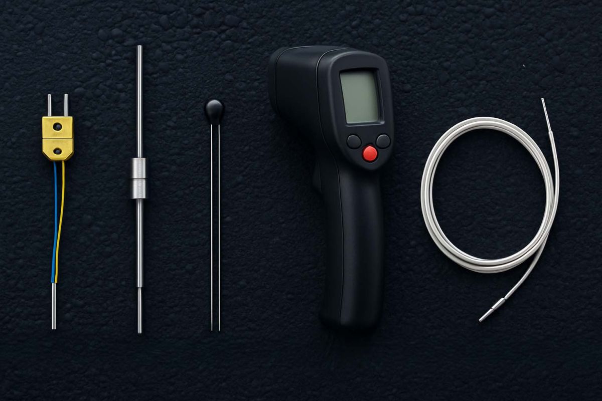
Various temperature sensors on a black background (from left: thermocouple, Pt100, NTC, IR thermometer, fiber optic sensor)

Introduction

Temperature is the most frequently measured physical quantity in industry and research. This guide explains the key measurement methods, shows when to use which sensor, how data acquisition works correctly, and what often goes wrong in practice, with concrete application examples from development and production.

1. Why measure temperature? The key use cases

Whether in development, quality assurance, or production, temperature measurement serves many critical functions in industrial applications. Here are the main areas at a glance:

Safety & quality

  • Overheating protection: prevents damage to expensive prototypes or production equipment
  • Process monitoring: in plastic injection molding, a few degrees decide between quality and scrap. Too cold leads to incomplete mold filling, too hot to material degradation
  • Materials testing: heat treatment of steel requires precise temperature control for the right hardness

Performance & efficiency

  • Thermal management: monitoring heat generation in power electronics, e-motors, and HV batteries to minimize losses and extend service life
  • Engine development: in combustion engines, oil that is too hot causes wear, oil that is too cold reduces efficiency; in e-motors, hot windings reduce performance and can permanently damage magnets
  • Battery testing: Li-ion cells age much faster above 40 °C, and during high-power fast charging (350 kW+), overheating can even lead to thermal runaway

Product development & testing

  • HALT/HASS tests: accelerated stress tests at extreme temperatures (−40 °C to +120 °C) reveal weak points in electronics before the product goes into production or reaches the customer
  • Endurance runs: bearings, gearboxes, or motors are tested for months at different temperatures
  • Condition monitoring: unusual temperature rises warn of impending failure

Practical tip: Temperature is often the first indicator of problems. A motor that suddenly runs 20 °C hotter than usual usually has a mechanical problem, long before other measured values stand out.

2. Contact vs. non-contact measurement: the basic decision

Temperatures can be captured either through direct thermal contact with the component or without contact via infrared. The choice depends on the process, accuracy, dynamics, and accessibility.
The first important decision: should the sensor touch the component or not?

Contact measurement

Advantages: high accuracy, measures the actual component temperature

Disadvantages: the sensor has to be mounted and can affect the system

Examples: thermocouple in the engine block, Pt100 in the cooling circuit, NTC sensor on the circuit board

Non-contact measurement (infrared)

Advantages: no intervention in the system, very fast, suitable for moving or hazardous parts

Disadvantages: measures surface temperature only; the reading depends heavily on the surface finish (bare metal "radiates" differently than black paint)

Examples: pyrometer for rotating brake discs, thermal imaging camera for control cabinets

At a glance:
Contact measurement = high accuracy at the desired measuring point; IR measurement = fast, contactless, flexible, but mind the emissivity

3. The key sensors in detail

The following sensor types cover most industrial applications. They differ in measuring principle, accuracy, dynamics, robustness, and integration effort.

Thermocouple (TC): the classic

Thermocouples are widespread and the "classic" for harsh environments, wide temperature ranges, and fast response. With their simple two-wire connection and standard connectors (thermocouple plugs), they are easy to replace and easy to source. They are also relatively inexpensive.

How a thermocouple works:

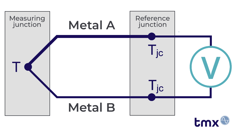
Thermocouples consist of two conductors made of different metals that are joined at the sensor tip. This is the measuring junction. Due to the Seebeck effect, a small voltage develops there that depends on the temperature at exactly this junction.

There is just one catch: they always measure only the temperature difference between the measuring junction and the connection point (terminals). To determine an absolute temperature, the temperature at the connection point must be known. In the past, this was solved with an ice bath, since it has a known temperature of 0 °C, which is where the term "cold junction compensation" comes from. In modern DAQ systems, a small temperature sensor (usually an RTD or thermistor) sitting directly at the connection point takes over this task. The software then calculates automatically: measured thermoelectric voltage + terminal temperature = actual temperature at the measuring point. In high-quality systems, CJC accuracy is ±0.5 °C.

The main thermocouple types:

There are many types of thermocouples, which differ in their metal pairings. Each pairing (type) has specific properties for temperature measurement. The most common types are:

  • Type K (nickel-chromium): the all-rounder up to approx. 1,260 °C. Ideal for furnaces, exhaust gas measurement, engine and turbine testing, and mechanical engineering
  • Type J (iron-constantan): up to approx. 760 °C, inexpensive but rusts easily. Common in older plants, bearing housings, and oil baths
  • Type T (copper-constantan): up to approx. 370 °C, very precise at lower temperatures. Ideal for climate chambers, cryostats, food and lab applications
  • Type E (NiCr-CuNi): high signal at low temperatures; refrigeration, calibration, and test stand tasks with small ΔT
  • Type N (NiCrSi-NiSi): particularly stable at high temperatures; ideal for long-term tests or the process industry
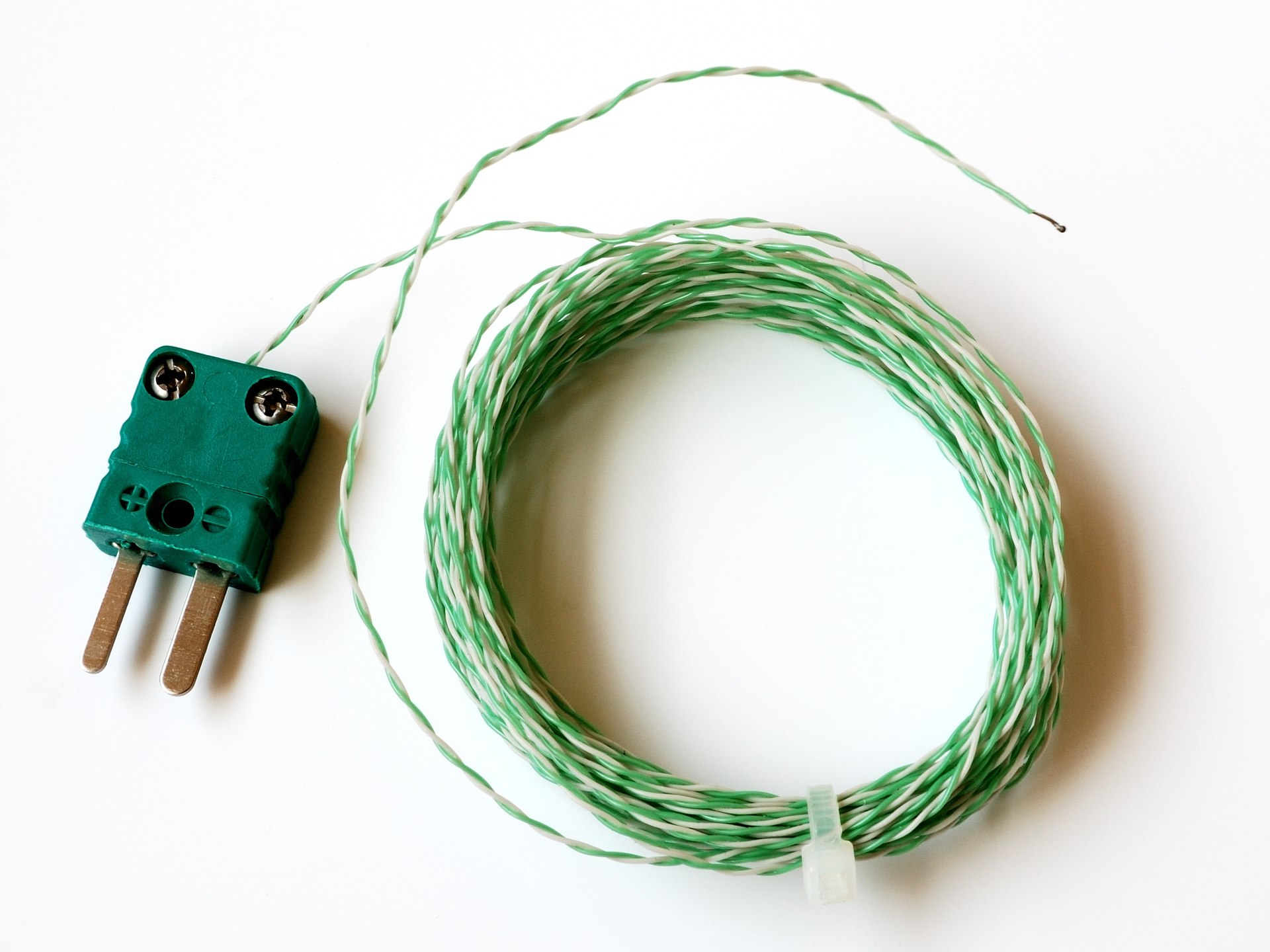
Type K thermocouple with coiled cable

Advantages:

  • Very wide temperature range (approx. −200 to over 1,000 °C)
  • Very robust, many designs, inexpensive
  • Fast response (especially with thin wires)

Disadvantages:

  • Signal only in the mV range (susceptible to interference, e.g., EMC from e-motors, HV)
  • Limited accuracy (typically ±1–2 °C)
  • Drifts at high temperatures

Resistance thermometers Pt100/Pt1000 (RTD)

Resistance thermometers are the standard for precise, stable measurements in labs, calibration, and industrial processes with high quality requirements.

How a resistance thermometer works:

Resistance thermometers, also called RTDs (resistance temperature detectors), use the property of metals that their electrical resistance changes with temperature. Platinum shows a highly reproducible, nearly linear characteristic.

A Pt100 has exactly 100 Ω at 0 °C and 138.5 Ω at 100 °C. A Pt1000 accordingly has 1,000 Ω at 0 °C. Above 0 °C, the behavior is approximately linear, which makes conversion into temperature values comparatively simple and accurate.

Important practical tip:

With Pt100 sensors, lead resistance distorts the result. With 10 meters of cable, this can quickly add up to an error of 2–3 °C, because the measuring current flows through the same two wires used for measurement. The lead resistance adds to the sensor resistance.

The solution, and in our view a must:
Use 3-wire or 4-wire connections. They separate the current paths so that only the actual sensor resistance is measured.

Application examples:

  • Climate chamber calibration: ±0.1 °C accuracy required
  • Engine oil temperature: long-term stability matters
  • Process monitoring: when insurers or standards require high accuracy
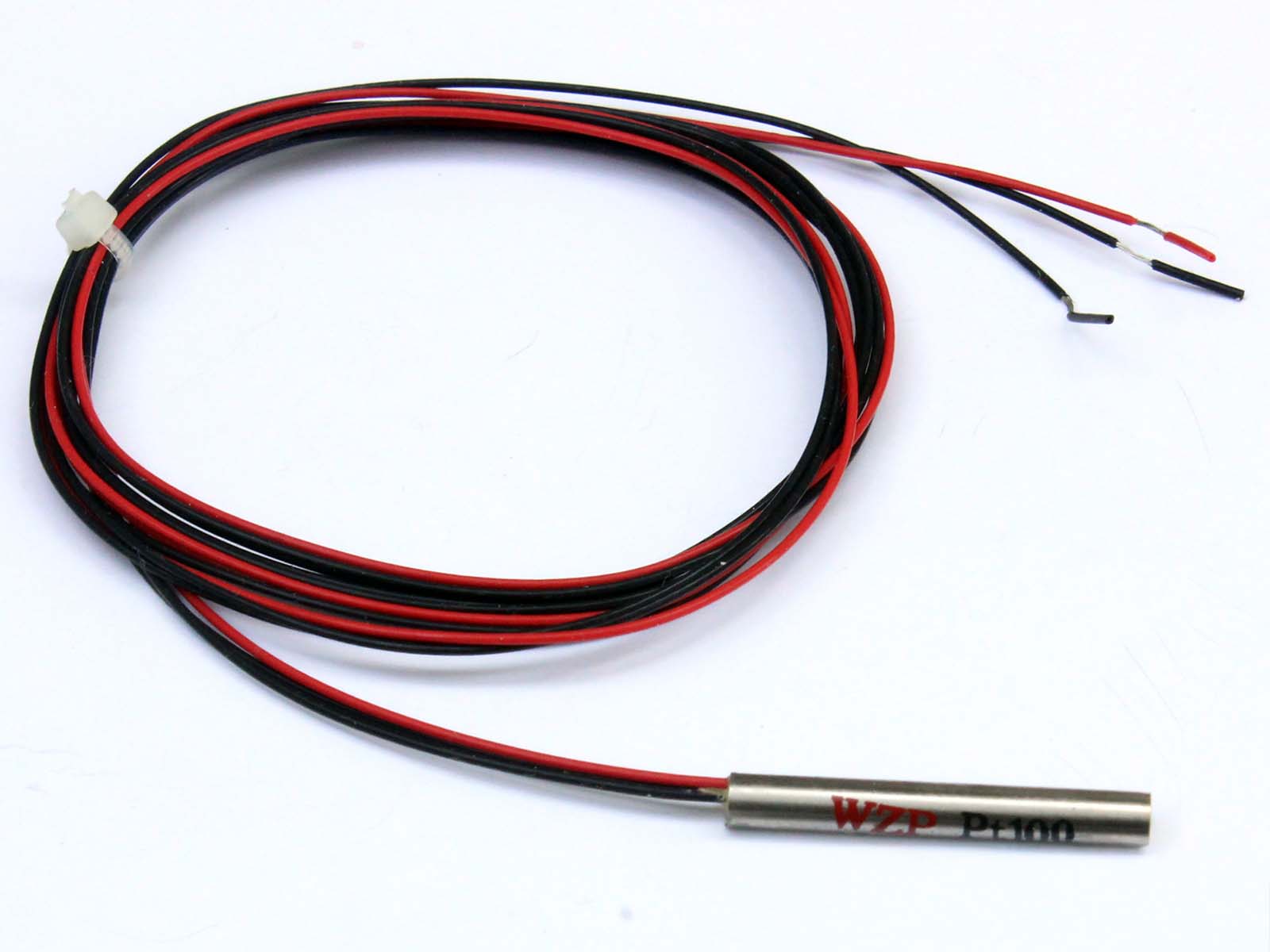
Silver Pt100 sensor with a black-black-red three-wire cable
By Suyash Dwivedi, own work, CC BY-SA 4.0, https://commons.wikimedia.org/w/index.php?curid=55447131

Advantages:

  • Very high accuracy (±0.1 °C possible) and repeatability
  • Excellent long-term stability
  • Linear and predictable

Disadvantages:

  • Self-heating if the measuring current is too high
  • Limited temperature range (−200 °C to ~600 °C)
  • More complex connection (3-/4-wire) than TCs
  • More expensive than thermocouples

Thermistors (NTC/PTC)

Thermistors suit applications that need high sensitivity, small size, and short response times, typically in electronics and devices.

How thermistors work

A thermistor is a semiconductor resistor whose value changes strongly and reproducibly with temperature (described, e.g., by the Steinhart-Hart equation). In NTC thermistors, resistance falls as temperature rises; in PTC thermistors, it rises. This characteristic is used to measure temperature.

Application examples:

  • Smartphone battery: monitoring charging temperature
  • CPU cooling: very fast response to load changes
  • Room temperature control: high resolution in the comfort range
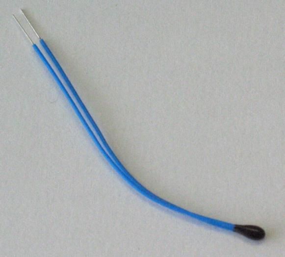
Two blue leads converging in a black sensing tip
Photo by Ansgar Hellwig, CC BY-SA 2.0 de, https://commons.wikimedia.org/w/index.php?curid=242719
Advantages:
  • Extremely sensitive (detects small temperature changes)
  • Can be made very small
  • Inexpensive and fast
Disadvantages:
  • Highly nonlinear (complex conversion)
  • Less accurate than RTDs and thermocouples
  • Small temperature range (usually −40 °C to +150 °C)
  • Can age or fail from overload
  • Can drift over time

Infrared pyrometers & thermography: non-contact

IR methods allow fast measurements without intervening in the process, or where the sensor cannot reach the measuring point. However, they capture only the surface temperature and depend heavily on the emissivity of the surface.

How IR measurement works

All bodies above absolute zero emit thermal radiation in the infrared range. An IR pyrometer or thermal imaging camera detects this radiation, filters out a specific wavelength band, and calculates the surface temperature from it. This is based on the Stefan-Boltzmann law and the emissivity of the surface.

Application examples:

  • Brake disc testing: measurement while driving
  • Plastic extrusion: temperature of the hot melt
  • Electronics development: finding hot spots on circuit boards

Practical notes: The biggest problem with IR measurement: different surfaces radiate with different intensity. A pyrometer "sees" polished aluminum at 100 °C as much cooler than matte black sheet metal at the same temperature. A practical trick is to apply an "emissivity patch" with a known emissivity (often close to 1.0) or to mark a small spot with matte black paint (emissivity ≈ 0.95).

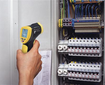
A hand holding an IR pyrometer aimed at an electrical distribution board to measure its temperature
By Trotec GmbH, http://www.trotec.de, public domain, https://commons.wikimedia.org/w/index.php?curid=22506538

Advantages:

  • Very fast (milliseconds)
  • No contact needed
  • Measurements on moving or hazardous parts possible

Disadvantages:

  • Surface temperature only
  • Emissivity must be known
  • Interference from smoke, dust, steam, or reflections possible

Fiber optic temperature sensors: EMC-proof and intrinsically safe

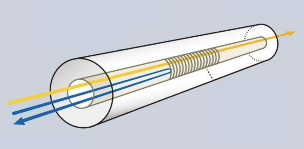
Drawing of an optical fiber with an interference grating that reflects light of a specific wavelength
Unknown author, https://www.tatsuta.com/product/sensor_medical/optical/fbg/, public domain, https://commons.wikimedia.org/w/index.php?curid=150236583

Compared with the sensors and methods described so far, fiber optic sensors are still relatively new, but for certain applications in EMC-critical, high-voltage, and explosion-hazard environments they are irreplaceable. They work without any electrical connection at the measuring point and are therefore intrinsically safe and immune to EMC. Two methods are currently used for temperature measurement with optical fibers:

a) Spectrometric method (Bragg grating)

A fiber Bragg grating (FBG) is inscribed into the glass fiber: a tiny grating that reflects light of a specific wavelength. This Bragg wavelength changes with temperature, because the refractive index and grating period depend on temperature. An interrogator (optical spectrometer) measures this shift and calculates the temperature. The temperature range depends on fiber and coating and is typically −40 to ~300 °C; special versions go higher.

Application examples:
  • EV battery: temperature monitoring in every cell without short-circuit risk
  • Chemical plant: explosion protection where standard electronics are prohibited
  • MRI scanner: strong magnetic fields would interfere with thermocouples
  • Wind turbine: temperature profile along a 50-meter rotor blade
  • High voltage: 400 kV transformers, high-voltage batteries
Advantages:
  • Completely EMC-proof and explosion-safe
  • Multiplexing: many measuring points per fiber (10–40 points)
  • Very small and light, so they can be used in tight spaces
  • Fast response
  • Corrosion-resistant
Disadvantages:
  • Expensive evaluation electronics (interrogator)
  • Also responds to mechanical strain (strain compensation required)
  • Less robust against mechanical stress than, e.g., thermocouples
  • More sensitive to tight bend radii
  • Not yet as widespread as conventional sensors

b) Intensity-based method

Here, the intensity of the light passing through or reflected back from the fiber changes depending on external influences (e.g., temperature, absorption, bending). The light absorption or loss in the sensor is measured, and the temperature is derived from it.

The temperature is captured at the end of the fiber, similar to thermocouples or RTDs. This makes the method particularly suitable for R&D and testing when measurements are needed in bores or at precisely defined points. Because the fibers can be made extremely thin, they can be integrated into tight gaps, for example directly in the windings of electric motors. Conventional sensors often reach their limits there, if only because of their size and the insulation required.

Application examples:
  • Temperature monitoring of individual components in high-voltage or hazardous areas (e.g., in train pantographs)
  • Measurements in motor windings, transformers, or drilled sensor holes
  • Cost-conscious projects with few measuring points
Advantages:
  • Lower-cost interrogators, needing only a light source and a simple detector
  • Robust technology, practical for individual, clearly defined measuring points
  • Very thin fibers possible → use in areas too narrow for thermocouples (e.g., motor windings)
  • Fast response
  • Corrosion-resistant
Disadvantages:
  • Only one measuring point per fiber
  • Also responds to mechanical strain (strain compensation required)
  • Less robust against mechanical stress than, e.g., thermocouples
  • Sensitive to tight bend radii
  • Less flexible than spectral FBG systems

Note: Besides the two methods described, there is also distributed fiber optic temperature sensing (DTS) via Raman/Brillouin scattering, which measures temperature continuously along a fiber, for example over long distances (e.g., pipeline monitoring). For test setups and test stands, FBG sensors are often the more practical solution because they measure temperature at a defined point (the grating).

4. Selection guide: which sensor type for what?

For dynamic processes, thermocouples and thermistors often have the edge. If a wide temperature range is needed, thermocouples are a good choice. For precision and long-term use, RTDs offer the best basis. IR scores when contact is impossible. Fiber optics are recommended for EMC/HV environments, explosion protection, or when many measuring points along a route are needed. The following table gives quick orientation along key selection criteria and typical applications.

Criterion Thermocouple RTD (Pt100/Pt1000) Thermistor (NTC) IR pyrometer Fiber optic (FBG) Fiber optic (intensity-based)
Temperature range very wide (−200…>1,000 °C) −200…~600 °C typ. −40…150 °C −50…>2,000 °C (material-dependent) typ. −40…~300 °C (coating-dependent), special versions higher typ. −40…~300 °C (depends on sensor design)
Accuracy medium high medium–high (narrow range) medium (ε-dependent) high (with calibration/packaging) solid, but sensitive to external influences
Response time fast medium very fast very fast very fast (low mass) very fast (end-point measurement)
Robustness high high medium high (optical) high (electrical)
medium (mechanical)
high (electrical)
medium (mechanical)
Cost low medium low higher high (interrogator) medium–high (simpler interrogator)
Typical applications exhaust, furnace, engine parts lab, calibration, process smartphone, electronics moving/hazardous parts such as brake discs ATEX, HV batteries, transformers single points in bores, motor windings, hazardous areas

5. Measurement chain & data acquisition: the complete system

The best sensor is useless if there are errors in the measurement chain. Only the right measurement chain, with suitable signal conditioning, digitization, synchronization, and processing, turns sensor signals into reliable temperature data. One important principle is differential measurement, that is, between the + and − lines. This reliably suppresses interference that occurs on both lines at the same time (e.g., 50/60 Hz mains hum).

Thermocouple measurement:

To use thermocouples reliably, the entire measurement chain from the sensor via the extension cable to the amplifier must be properly planned.

What you need:

  • Thermocouple matched to the temperature range and dynamics
  • Extension cable of the same type (not copper!)
  • Matching TC connector made of thermocouple alloy
  • Cold junction compensation (CJC) at the reference point
  • Low-noise measurement amplifier with anti-aliasing filter (AAF)
  • Differential, galvanically isolated input

Cold junction compensation (CJC): Modern DAQ systems and instruments already have CJC built in. You just select the right thermocouple type in the software and enable CJC. Problems usually arise only with simple handheld meters, homemade electronics, or when the CJC function has been disabled by mistake.

Practical tips:

  • Extension cables: Use only extension cables of the same type. Type K needs K cables (green), type J needs J cables (black) (IEC 60584 color codes). A copper cable creates an additional material junction and thus an unwanted "mini thermocouple". The same applies to connectors.
  • Shielding & routing: Route TC cables twisted and shielded. Keep sufficient distance (min. 30 cm) from power cables. Connect the shield according to a defined grounding concept (e.g., at one end, on the DAQ side).
  • EMC protection: Thermocouple measurement deals with mV signals. That requires particularly low-noise amplifiers with differential inputs to reduce common-mode and ground loop errors.
  • Bandwidth/sampling rate: Match the sampling rate to the signal dynamics; this also actively suppresses 50/60 Hz interference.

Common errors and solutions:

  • Problem: temperature consistently too low
    Solution: CJC not enabled in the software or wrong TC type selected.
  • Problem: values fluctuate strongly → copper or wrong extension cable used, which creates additional thermoelectric voltages.
    Fix: always use extension cables of the matching type.
  • Problem: 50 Hz hum in the data →
    Solution: shielded cables, differential inputs
  • Problem: nonlinear deviations at high temperatures
    Solution: store the correct thermocouple characteristic in the software
  • Problem: sluggish temperature change → probes too thick or air gap
    Fix: thin probes, probe directly on the measuring point (no air gap); use thermal paste if needed.

Measuring with RTDs/Pt100

With RTDs such as the Pt100, correct wiring and linearization above all determine the precision of the measurement chain.

What you need:

  • RTD in a suitable accuracy class (A, B, or 1/3 DIN)
  • 3-wire or 4-wire connection for lead compensation
  • Suitable measuring current (usually 1 mA)
  • Good thermal coupling
  • Correct linearization in the measurement software

Understanding 3-wire vs. 4-wire:

  • 2-wire: acceptable only with short cables (< 1 m)
  • 3-wire: standard for most applications, compensates lead resistance
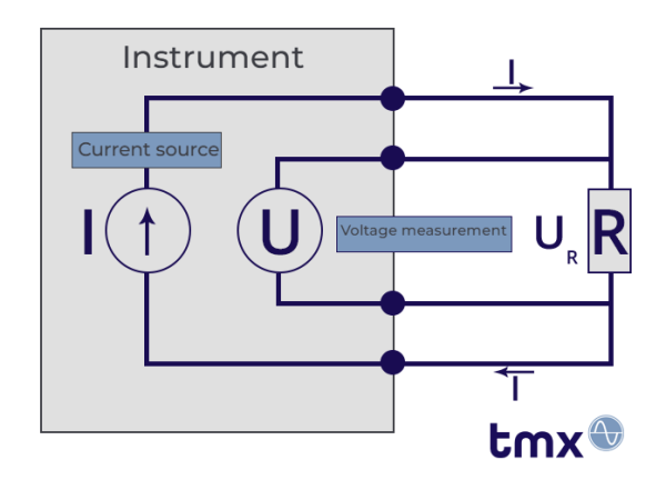
  • 4-wire: highest accuracy, separate supply and sense lines
Diagram of a 4-wire circuit with current source and voltage measurement

Don't underestimate linearization:

RTDs are not linear! The Callendar-Van Dusen equation describes the real behavior. Many systems use simplified linear approximations, which leads to errors of several degrees over larger temperature ranges.

When simple linearization is enough:

  • Small temperature range (< 100 K)
  • Lower accuracy requirements (> ±1 °C)

When you need the correct CVD equation:

  • Large temperature range (−50 °C to +400 °C)
  • High accuracy required (< ±0.5 °C)
  • Calibrated sensors with certificate

Practical tips:

  • Limit the measuring current: 1 mA is usually optimal. At 10 mA, a Pt100 already heats itself noticeably.
  • Optimize coupling: use thermal paste, defined contact pressure, document insertion depth.
  • Mind the mechanics: avoid strain on the sensor element, as it distorts the measurement.

Common errors and fixes:

  • Problem: values 2–3 °C too low
    Solution: compensate lead resistance with 3/4-wire
  • Problem: sensor shows temperatures too high
    Solution: reduce measuring current (self-heating)
  • Problem: systematic deviation over large temperature ranges
    Solution: use CVD linearization instead of a simple linear approximation
  • Problem: unstable values
    Solution: improve thermal coupling, thermal paste

Non-contact measurement with IR pyrometers & thermography

With non-contact methods, the optical chain from the measuring spot to evaluation is decisive for correct results. They are particularly suited to moving, hot, or hazardous components.

What you need:

  • Suitable wavelength band for material and temperature
  • Correct emissivity (ε) for the surface
  • Suitable optics (distance-to-spot ratio)
  • For thermography: defined frame rate and region of interest (ROI)

Example:

On a rotating shaft, the temperature is captured with a short-wavelength IR pyrometer. A matte marking prevents reflection errors.

Practical tips:

  • Mind the spot size: a 10:1 pyrometer measures a 10 cm circle at 1 m distance, not just a point
  • Measuring angle: measure as perpendicular to the surface as possible, avoid reflections
  • Atmosphere: dust, steam, or smoke between sensor and object distort the measurement

Common errors and fixes:

  • Problem: systematically low values
    Solution: emissivity set too low
  • Problem: values jump wildly
    Solution: spot too large, "sees" the surroundings too
  • Problem: shiny surfaces
    Solution: apply a matte reference mark

Fiber optic temperature measurement

FBG sensors work without an electrical connection and are suited to high voltage, strong EMC, and hazardous areas. Fiber optic sensors also need a matched measurement chain, from the sensor grating via the fiber to the interrogator.

What you need:

  • FBG sensor (several sensors per fiber possible, depending on the method)
  • Suitable sensor packaging and coupling
  • Optical interrogator (evaluation unit)
  • Mechanically protected fiber routing

Special features:

FBG sensors respond to both temperature and mechanical strain. For pure temperature measurement, you need strain-compensated FBGs or mechanically decoupled mounting.

Practical tips:

  • Mind the bend radius: at least 10 × fiber diameter, otherwise signal loss and breakage are possible
  • Use multiplexing: up to 40 sensors on one fiber saves cabling
  • Choose the coating according to chemistry and temperature (acrylate, polyimide, metal)

Common errors and fixes:

  • Problem: temperature "jumps" under mechanical load
    Solution: use a strain-compensated design
  • Problem: signal loss
    Solution: increase bend radius, check splices
  • Problem: sensor does not respond
    Solution: check the interrogator's wavelength range

Application example: In an HV battery module, several FBGs are routed on one fiber along the cell rows. The interrogator captures all measuring points synchronously and galvanically isolated from the high-voltage system.

Data acquisition & logging of temperature sensors

Regardless of sensor type, acquisition must deliver the bandwidth, isolation, and time base the application requires.

Helpful guidelines:

  • The sampling rate is at least 2.5 times the highest signal frequency
  • An anti-aliasing filter per channel prevents distortion (aliasing)
  • Galvanically isolated signal inputs avoid ground loops between sensors. This is particularly important with non-isolated thermocouples mounted directly on the test object
  • Instruments are synchronized so that a common clock applies to all channels and devices and time-correct data are produced
  • Use triggers (pre/post) for event-based recording

Important note: 24-bit resolution on the data sheet does not automatically mean high measurement quality. Optimize the analog foundation (sensor, amplifier, cabling) first, then make use of the digital capabilities.

Common error sources & how to avoid them

There are recurring error sources that can be reliably controlled with a few principles.

Problem: sensor shows fluctuating values

Causes:

  • Loose contact in the connection
  • EMC interference (especially with thermocouples)
  • Sensor poorly coupled to the test object

Solution:

  • Check all connectors
  • Use shielded cables and separate cable routes for measurement and power circuits
  • Thermal paste between sensor and component

Problem: readings consistently too high/too low

Causes:

  • Missing or wrong cold junction compensation (thermocouple)
  • Self-heating (RTD with measuring current too high)
  • Wrong emissivity (IR)

Solution:

  • Enable and calibrate the CJC function in the instrument
  • Reduce measuring current (≤ 1 mA for Pt100)
  • Determine emissivity with a reference measurement

Problem: sensor responds very slowly

Causes:

  • Thermal mass too large (thick sheath)
  • Poor thermal coupling
  • Filters in the measurement chain set too slow

Solution:

  • Use a thinner sensor
  • Direct contact without a protection tube (if possible)
  • Check filter time constants

Quick calculations for everyday use

Quick estimates support design and serve as plausibility checks during testing.

Thermocouple (type K)

Rule of thumb: The sensor delivers approx. 40 µV (0.00004 V) per kelvin.
Example: A temperature difference of 100 °C corresponds to a 4 mV (0.004 V) signal.
Practical tip: The amplifier should amplify at least 10 times, giving you 0.4 mV/K, which is easy to measure.

Pt100

Rule of thumb: approx. 0.4 Ω per kelvin
Example: At 100 °C, a Pt100 has about 138 Ω instead of 100 Ω at 0 °C
Practical tip: 1 mA measuring current → 0.4 mV/K signal change

Estimating sensor response times

Thermocouple (0.2 mm) in air: τ ≈ 0.1–0.5 s
Pt100 with protection tube in liquid: τ ≈ 1–10 s
Infrared pyrometer: τ < 0.1 s

τ (tau) = time until 63 % of a step change in temperature is captured.

Sensor selection checklist

The checklist helps you capture requirements in a structured way and narrow down options systematically.

  • Temperature range (min/max/dynamics)
  • Accuracy requirement
  • Installation environment (vibration, humidity, chemicals, high voltage)
  • Cable lengths and EMC requirements
  • Budget and schedule
  • Maintenance and calibration

Keep in mind during implementation:

  1. Correct extension cables ordered
  2. CJC provided for thermocouples
  3. 3-wire or 4-wire connection planned for RTDs
  4. Emissivity determined for IR measurement
  5. EMC concept created (shielded cables, separate routes)
  6. Calibration/verification scheduled

Practical application examples

Engine test stand

Task: monitor oil temperature, coolant, exhaust gas

Solution:

  • Oil temperature: Pt100 with 4-wire (±0.2 °C accuracy for standard compliance)
  • Coolant in/out: 2× Pt100 (calculate efficiency)
  • Exhaust gas: robust type K thermocouple up to 800 °C
Electronics development

Task: find hot spots on circuit boards

Solution:

  • Initial analysis: thermal imaging camera (overview of the entire board)
  • Detailed measurement: miniature thermocouples or IR pyrometer with a small spot
  • Continuous measurement: NTC thermistors on critical ICs

Chemical plant (explosion protection)

Task: reactor temperature in a hazardous area

Solution:

  • FBG fiber optic sensors (intrinsically safe)
  • Alternative: ATEX-certified thermocouples with isolating barriers
  • Multiple redundancy for safety-related shutdowns

HV batteries (traction batteries)

Task:

Monitor cell temperature, cooling circuit, and thermal runaway management

Solution:

  • Cell temperature: insulated HV type T thermocouples (Cu-CuNi) with ceramic insulation up to 1,000 V, thermally coupled to the cell housing via insulating thermal pads
  • Alternative cell measurement: FBG sensors, potential-free, several measuring points per fiber possible, EMC-immune
  • Cooling circuit: 2× Pt1000 in coolant supply and return (galvanically isolated from the HV system)

Typical costs and lead times

Rough guide (as of 2025):

  • Thermocouples: €20–100 (standard), €200–500 (special designs)
  • Pt100: €50–200 (standard), €300–800 (precision/hygienic)
  • IR pyrometer: €200–2,000 (spot meter), €5,000–50,000 (thermal imaging camera)
  • FBG fiber optic: €200–500 per sensor, €3,000–20,000 for the interrogator

Lead times:

  • Standard sensors: 1–4 weeks
  • Custom designs: 6–12 weeks
  • Fiber optic systems: 8–16 weeks

Conclusion: the right temperature measurement for your project

There is no "best" temperature sensor, only the best one for your specific application:

  • For harsh environments and high temperatures: thermocouples (especially type K)
  • For highest accuracy and stability: Pt100/1000 with 4-wire connection
  • For small, sensitive electronics: NTC thermistors
  • For moving or inaccessible parts: IR pyrometers
  • For EMC-critical or hazardous environments: FBG fiber optic sensors

The most important tip:
The measurement chain is decisive! The most expensive sensor is useless if cold junction compensation, amplification, or calibration are wrong.
For beginners: start with standard thermocouples or Pt100; they solve 90 % of all tasks. Special sensors such as FBG are for very specific problems.

YOUR NEXT STEP

Get in touch

We look forward to learning about your test and measurement tasks and developing solutions together that take your projects to the next level.

Back to the news overview

About us

TMX Solutions provides custom measurement, test and control solutions for complex requirements in research and development. Our experienced team develops systems that deliver precision and long-term value: independent, innovative and customer-focused.

Contact

TMX Solutions GmbH
Bachseifenweg 10
61169 Friedberg
Germany

Stay in touch

Subscribe to our newsletter (German) and follow us on

 
Copyright 2026 TMX Solutions. All rights reserved.
Settings saved
Privacy settings

This website may use cookies for statistics and marketing purposes.

Technically required cookies are always loaded.

The following cookies may be set depending on your settings:

user_privacy_settings

Domain name: tmx-solutions.com
Expiry: 30 days
Storage: Local storage
Description: Stores the privacy settings from the "Privacy Manager" consent tool.

user_privacy_settings_expires

Domain name: tmx-solutions.com
Expiry: 30 days
Storage: Local storage
Description: Stores the expiry of the privacy level settings from the "Privacy Manager" consent tool.

ce_popup_isClosed

Domain name: tmx-solutions.com
Expiry: 30 days
Storage: Local storage
Description: Stores that the user closed the popup (content element "Popup").

Eclipse.outdated-browser: "confirmed"

Domain name: tmx-solutions.com
Expiry: 30 days
Storage: Local storage
Description: Stores the state of the "Outdated browser" notice bar.
Development & implementation
 
The TMX project workflow

Professional project management you can rely on

 
TMX technology

Discover the technology behind our test systems.

You are using an outdated browser. The website may not be displayed correctly.